Community
Civil 3D Forum
Welcome to Autodesk’s Civil 3D Forums. Share your knowledge, ask questions, and explore popular AutoCAD Civil 3D topics.
Turn on suggestions
Auto-suggest helps you quickly narrow down your search results by suggesting possible matches as you type.
Reply
Topic Options
- Subscribe to RSS Feed
- Mark Topic as New
- Mark Topic as Read
- Float this Topic for Current User
- Bookmark
- Subscribe
- Printer Friendly Page
- « Previous
-
- 1
- 2
- Next »
Message 1 of 24
10-30-2013
09:16 AM
- Mark as New
- Bookmark
- Subscribe
- Mute
- Subscribe to RSS Feed
- Permalink
- Report
10-30-2013
09:16 AM
Hi Guys,
I am currently working on a Stream Restoration project and am really struggling to find a flexible solution for modelling natural river corridors.
My Landscape Architect has provided me with a set of 2d-Polylines representing the proposed river alignment as well as some embankment lines. (Spline.jpg)
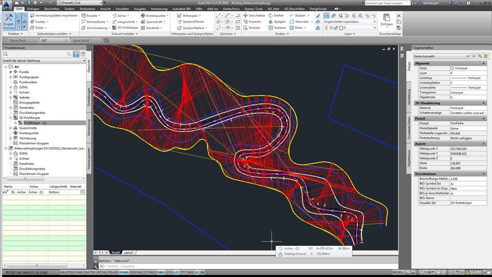
My first attempt was to create a corridor with a cross-section consisting of some generic links targeting my polylines. Please see attachment (Corridor.jpg). Obviously it results in a total mess. So I tried splitting the corridor in multiple sub-corridors targeting different lines as suggested by Dana Probert in her class on Stream Restoration. (Corridor1.jpg) However, given the curvature of these lines, the corridor simply never works as expected.
Question #1: is there any way to create a ‘smart subassembly’ which would prevent those bowties? Ideally I’d like it to be able to connect to subsequent vertices of the targeted line. Maybe the subassembly composer is capable of doing such magic tricks?
Since the corridor approach didn’t work I tried adding the Polylines as breaklines to a surface without any other definition. To assign some elevation data I converted them to Feature Lines. The original 2d-Polylines have been set to Fit -> Quadratic though and Civil 3d just refuses to accept them as they are. So I’d go splineedit -> convert to spline and then Flatten to convert them to Polylines back again.
This way I can convert my Polylines to Feature Lines, assign elevations in the elevation editor and add them to an empty surface. After playing around with the mid-ordinate distance and interpolation values I end up with something usable but difficult to manage (Surface feature line.jpg). The Flatten command converts my beautiful splines to a set of interconnected lines and arcs, which aren’t that easy to control. And for all this effort the resulting surface isn’t as smooth as expected (Object viewer.jpg).
Question #2: is there a way to convert splines to feature lines, or better yet – add splines as breaklines to a surface and derive their elevation from a profile?
My current solution to this problem is converting the 2d-Polylines to splines, and then back to Polylines via Splineedit. This way I get a Polyline with tons of straight but short segments. I convert them to feature lines, assign elevations and add as breaklines to the surface definition. The resulting surface is super smooth. It just isn’t easy to modify because of the amount of vertices that have to be moved to do any adjustments.
Question #3: Do you know of any better ways to approach this subject? All of the methods I’ve tried would have worked perfectly with a simple corridor. It’s the curvature that renders them useless.
Solved! Go to Solution.
Solved by sboon. Go to Solution.
23 REPLIES 23
Message 21 of 24
11-18-2013
05:29 AM
- Mark as New
- Bookmark
- Subscribe
- Mute
- Subscribe to RSS Feed
- Permalink
- Report
11-18-2013
05:29 AM
Thanks a lot Steve. This is exactly what I've been looking for.
I do apologise for my late reply - it's just that I have been away from the office for last two weeks.
Message 22 of 24
06-09-2014
09:02 AM
- Mark as New
- Bookmark
- Subscribe
- Mute
- Subscribe to RSS Feed
- Permalink
- Report
06-09-2014
09:02 AM
Im doing the same.. can you do a step by step to create your what you have in object viewer? thanks
Message 23 of 24
06-09-2014
08:15 PM
- Mark as New
- Bookmark
- Subscribe
- Mute
- Subscribe to RSS Feed
- Permalink
- Report
06-09-2014
08:15 PM
Hey Allen, as a surveyor how do you stake out a "Spine"? 🙂
Joe Bouza
Did you find this post helpful? Feel free to Like this post.
Did your question get successfully answered? Then click on the ACCEPT SOLUTION button.
Message 24 of 24
06-10-2014
05:32 AM
- Mark as New
- Bookmark
- Subscribe
- Mute
- Subscribe to RSS Feed
- Permalink
- Report
06-10-2014
05:32 AM
@Joe-Bouza wrote:
Hey Allen, as a surveyor how do you stake out a "Spine"? 🙂
Spine, Spline? In the old days. No. We'd cheat by breaking it in to multiple compound curves. Today. No problem! But we don't usually use them in County Road. They're more prevalent in Interstate design. Although I occasionally try to convince them to use splines in a drainage run to dissipate force. ![]()
Allen
Allen Jessup
CAD Manager - Designer
Did you find this post helpful? Feel free to Like this post.
Did your question get successfully answered? Then click on the ACCEPT SOLUTION button.
- « Previous
-
- 1
- 2
- Next »
Reply
Topic Options
- Subscribe to RSS Feed
- Mark Topic as New
- Mark Topic as Read
- Float this Topic for Current User
- Bookmark
- Subscribe
- Printer Friendly Page
- « Previous
-
- 1
- 2
- Next »

