Community
Civil 3D Forum
Welcome to Autodesk’s Civil 3D Forums. Share your knowledge, ask questions, and explore popular AutoCAD Civil 3D topics.
Turn on suggestions
Auto-suggest helps you quickly narrow down your search results by suggesting possible matches as you type.
Reply
Topic Options
- Subscribe to RSS Feed
- Mark Topic as New
- Mark Topic as Read
- Float this Topic for Current User
- Bookmark
- Subscribe
- Printer Friendly Page
Message 1 of 9
09-20-2013
11:49 AM
- Mark as New
- Bookmark
- Subscribe
- Mute
- Subscribe to RSS Feed
- Permalink
- Report
09-20-2013
11:49 AM
Slope Symbols for 3d Polylines
I use slope symbols instead of contours to keep my maps less busy. Unfortunetly I can only change my cut style and fill style to slope symbols with grading by right clicking on the little diamond in the grading and selecting grading properties.
I have created a surface with 3d poly lines not by creating grading and got contours that way, How can I create the slope symbols in a surface. I tried xploding them and then creating a block and using the measure tool on the 3d polylines but it doesnt do anything.
Picture 01 is the contours
Picture 1 is the contours turned off and cut/fill styles turned to slope symbols.
i am using civil 3d 2010
thanks
8 REPLIES 8
Message 2 of 9
09-20-2013
08:11 PM
- Mark as New
- Bookmark
- Subscribe
- Mute
- Subscribe to RSS Feed
- Permalink
- Report
09-20-2013
08:11 PM
This might not be the solution you're looking for, but it would be a time saver if you have a pretty good stretch of grading to mark.
You could do this with a simple corridor using LinkWidthandSlope subassemblies. Depending on how perpendicular the slope markers need to be, make a fake alignment that runs roughly parallel to the feature lines (or else spend the time to stepped offset, explode, convert to 2d, etc if you have to be perfect.) Make a profile that runs generally along the same elevation range as the feature lines.
Create an assembly that uses LinkWidthandSlope to target from the fake centerline to the first feature line. The next LinkWidthandSlope subassy will target the outside feature line.
After you run the corridor, go to Corridor Properties and then Slopes tab. Add your slope pattern. The program will ask you to pick which corridor feature lines to use. Pick them.
If those feature lines change, just rebuild the corridor and the slope markers will update (or leave the corridor on rebuild automatic, that's your call.)
Best regards,
Tim
Tim Corey
MicroCAD Training and Consulting, Inc.
Redding, CA
Autodesk Gold Reseller
New knowledge is the most valuable commodity on earth. -- Kurt Vonnegut
Message 3 of 9
09-20-2013
10:13 PM
- Mark as New
- Bookmark
- Subscribe
- Mute
- Subscribe to RSS Feed
- Permalink
- Report
09-20-2013
10:13 PM
How about the old school way of just manually placing blocks as needed?
Neil Wilson (a.k.a. neilw)
AEC Collection/C3D 2024, LDT 2004, Power Civil v8i SS1
WIN 10 64 PRO
http://www.sec-landmgt.com
AEC Collection/C3D 2024, LDT 2004, Power Civil v8i SS1
WIN 10 64 PRO
http://www.sec-landmgt.com
Message 4 of 9
09-21-2013
06:28 AM
- Mark as New
- Bookmark
- Subscribe
- Mute
- Subscribe to RSS Feed
- Permalink
- Report
09-21-2013
06:28 AM
or you could use the grading i lieu of the 3dplines? Seems to me if you can create the 3d plines then you could create the grading, no?
Joe Bouza
Did you find this post helpful? Feel free to Like this post.
Did your question get successfully answered? Then click on the ACCEPT SOLUTION button.
Message 5 of 9
09-21-2013
10:09 AM
- Mark as New
- Bookmark
- Subscribe
- Mute
- Subscribe to RSS Feed
- Permalink
- Report
09-21-2013
10:09 AM
What happens if the TOS and BOS are connected FL's that you infill and grab the diamond?
Joe Bouza
Did you find this post helpful? Feel free to Like this post.
Did your question get successfully answered? Then click on the ACCEPT SOLUTION button.
Message 6 of 9
09-22-2013
09:11 AM
- Mark as New
- Bookmark
- Subscribe
- Mute
- Subscribe to RSS Feed
- Permalink
- Report
09-22-2013
09:11 AM
This is a pet hate of mine. You can't create these manually with existing lines. I have asked before for a tool or how (if) the survey feature does it.
Why go through the riggers of recreating it for the sake of a few blocks.
I have wrote a tool which kind of works for this. Perhaps I need to learn to publish it too. I'll look into it when I can.. Watch this space. Ps any proceeds will go to my daughter.
Why go through the riggers of recreating it for the sake of a few blocks.
I have wrote a tool which kind of works for this. Perhaps I need to learn to publish it too. I'll look into it when I can.. Watch this space. Ps any proceeds will go to my daughter.
Mike Evans
Civil3D 2022 English
Windows 7 Professional 64-bit
Intel(R) Core(TM) i7-3820 CPU @ 3.60GHz (8 CPUs), ~4.0GHz With 32768MB RAM, AMD FirePro V4900, Dedicated Memory: 984 MB, Shared Memory: 814 MB

Civil3D 2022 English
Windows 7 Professional 64-bit
Intel(R) Core(TM) i7-3820 CPU @ 3.60GHz (8 CPUs), ~4.0GHz With 32768MB RAM, AMD FirePro V4900, Dedicated Memory: 984 MB, Shared Memory: 814 MB
Message 7 of 9
09-23-2013
12:43 AM
- Mark as New
- Bookmark
- Subscribe
- Mute
- Subscribe to RSS Feed
- Permalink
- Report
09-23-2013
12:43 AM
I've used this which works fairly well most of the time - not tried with 3D polys though
neilyj (No connection with Autodesk other than using the products in the real world)
Did you find this post helpful? Feel free to Like this post.
Did your question get successfully answered? Then click on the ACCEPT SOLUTION button.
AEC Collection 2024 UKIE (mainly Civil 3D UKIE and IW)
Win 11 Pro x64, 1Tb Primary SSD, 1Tb Secondary SSD
64Gb RAM Intel(R) Xeon(R) W-11855M CPU @ 3.2GHz
NVIDIA RTX A5000 16Gb, Dual 27" Monitor, Dell Inspiron 7760
Message 8 of 9
08-25-2015
11:01 AM
- Mark as New
- Bookmark
- Subscribe
- Mute
- Subscribe to RSS Feed
- Permalink
- Report
08-25-2015
11:01 AM
I use leaders with arrow "Datum triangle filled" and "Datum triangle", and place them where I want it, it takes time, but you have more control over it.
Message 9 of 9
08-25-2015
12:56 PM
- Mark as New
- Bookmark
- Subscribe
- Mute
- Subscribe to RSS Feed
- Permalink
- Report
08-25-2015
12:56 PM
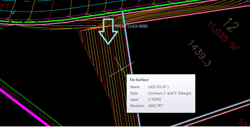
There is a tool in Gizmo3D that creates these by simply picking the lower and upper 3D Figures (3dPolys, FeatureLines). Here is a Dialog & Graphic Example.
Why not try the full working 60-day no cost evaluation to get them done?
Reply
Topic Options
- Subscribe to RSS Feed
- Mark Topic as New
- Mark Topic as Read
- Float this Topic for Current User
- Bookmark
- Subscribe
- Printer Friendly Page

