Community
Civil 3D Forum
Welcome to Autodesk’s Civil 3D Forums. Share your knowledge, ask questions, and explore popular AutoCAD Civil 3D topics.
Turn on suggestions
Auto-suggest helps you quickly narrow down your search results by suggesting possible matches as you type.
Reply
Topic Options
- Subscribe to RSS Feed
- Mark Topic as New
- Mark Topic as Read
- Float this Topic for Current User
- Bookmark
- Subscribe
- Printer Friendly Page
Message 1 of 6
09-01-2011
02:02 AM
- Mark as New
- Bookmark
- Subscribe
- Mute
- Subscribe to RSS Feed
- Permalink
- Report
09-01-2011
02:02 AM
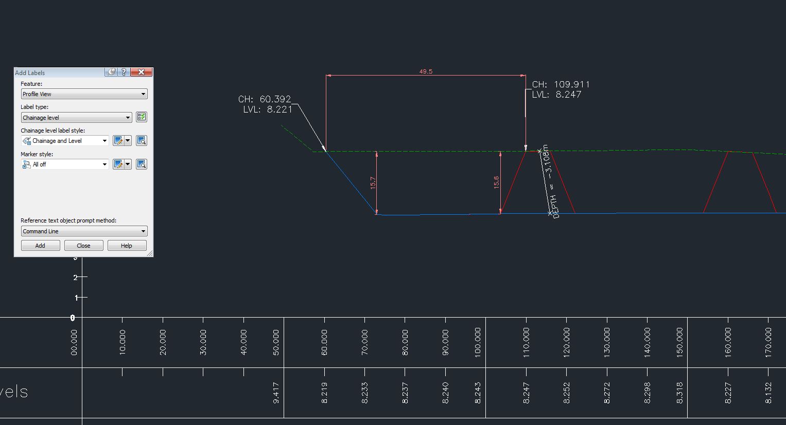
I need to label a profile similar to the screenshot and have a couple of queries
I can create labels as shown in white but I want to show the horizontal distance (illustrated by dimension object) as a label - can this be done??
The depth is more problematic as I can't get the label to snap perpendicularly to show a true depth - can this be done??
I have used dimension objects again but they show the incorrect depth to to vertical exaggeration but I presume the cure is to create a dimstyle with a suitable factor (0.2 in this case)??. If I change the vertical exaggeration though, the dimensions lose their place (as expected) and I want to avoid this if possible
Thanks
neilyj (No connection with Autodesk other than using the products in the real world)
Did you find this post helpful? Feel free to Like this post.
Did your question get successfully answered? Then click on the ACCEPT SOLUTION button.
AEC Collection 2024 UKIE (mainly Civil 3D UKIE and IW)
Win 11 Pro x64, 1Tb Primary SSD, 1Tb Secondary SSD
64Gb RAM Intel(R) Xeon(R) W-11855M CPU @ 3.2GHz
NVIDIA RTX A5000 16Gb, Dual 27" Monitor, Dell Inspiron 7760
Solved! Go to Solution.
Solved by CivilFF. Go to Solution.
5 REPLIES 5
Message 2 of 6
09-08-2011
06:45 AM
- Mark as New
- Bookmark
- Subscribe
- Mute
- Subscribe to RSS Feed
- Permalink
- Report
09-08-2011
06:45 AM
1. Choose Home and select Toolspace,
2. Next select from the Profile View node - Label Styles and choose Station Elevation,
3. Click the right mouse button on Expressions and create a new Expression give it a meaningful name e.g. VerticalScale,
4. Create a new Expression,

{Drawing Scale Conversion}/10
where:
- DrawingScale Conversion is a current drawing scale and if you change
this scale in your drawing your label will recalculate VerticalScale automatically,
- Value 10 is the vertical exaggeration value used in your Profile View,
5. Create a new Expression and give it a meaningful name e.g. Dist1,

({Profile1Elevation}-{Profile View Point Elevation})/VerticalScale
where:
- Profile1 Elevation is the elevation of the first chosen profile,
- Profile View Point Elevation is the current elevation of the Label Insertion Point
which will be used assistantly,

6. Create a new Expression and give it a meaningful name e.g. Dist2,

({Profile2 Elevation}-{Profile View Point Elevation})/VerticalScale
where:
- Profile2 Elevation is the elevation of the second chosen profile,
- Profile View Point Elevation is the current elevation of the Label Insertion Point
which will be used assistantly,

7. Create a new Label and give it a meaningful name e.g. VerticalDistance,
8. Delete all the elements of this new Label and create your own,

9. Add a new Block element and give it a meaningful name e.g. B1,

change the following properties:
- Name =B1
- Anchor Point = Middle Center
- Block name = _Wipeout_Circle
- Y Offset = Dist1
10. Add a new Block element and give it a meaningful name e.g. B2,

change the following properties:
- Name = B2
- Anchor Point = Middle Center
- Block name = _Wipeout_Circle
- Y Offset = Dist2
11. Add a new Line element and give it a meaningful name e.g. Line,

change the following properties:
- Name = Line
- Start Point Anchor Component = B1
- Start Point Anchor Point = MiddleCenter
- Use End Point Anchor = True
- Start Point Anchor Component = B2
- Start Point Anchor Point = MiddleCenter
12. Add a new Text element and give it a meaningful name e.g. VertDist
change the following properties:
- Name = VertDist
- Anchor Component = Line
- Anchor Point = Middle
- Attachment = Top Center
- Contents : change the contents properties

choose from the list above:
Profile1Elevation Minus Profile2 Elevation
add any description text e.g. H= and unit
H=<[Profile1 Elevation Minus Profile2 Elevation(Um|P2|RN|AP|GC|UN|Sn|OF)]>m
13. When you do this click the OK button twice to close Text Component Editor
and Label Style Composer,
14. Add this newly created Label to your drawing,
15. Select the Add Labels function from Annotate,

16. Next choose from the feature ProfileView label - VerticalDistance type and add Label to your Profile View,
- select a profile view,
- specify station,
- specify elevation,
17. Now select this newly added Label and choose its Properties,

18. Select Profile1 Object and choose the green box icon to select your first Profile
from the Profile View and click the Enter button to confirm your selection,
19. Select Profile2 Object and choose the green box icon and select your second
Profile form the Profile View and click the Enter button to confirm your selection,

20. Move the Label to any chosen location,

Extra Options:
21. If you want to change the design of this label you can add Arrows and hide Blocks B1 and B2 then your label will
look like Linear Dimension,
22. Select the Label and choose the Edit option,
23. Add a new Block element and give it a meaningful name e.g. Arr1,

change the following properties:
- Name = Arr1
- Anchor Component = B1
- Anchor Point = Middle Center
- Block Name =_ClosedFilled
- Block Height = 1.50 mm
- Block Angle = 90.000(d)
24. Add a new Block element and give it a meaningful name e.g. Arr2,

change the following properties:
- Name = Arr2
- Anchor Component = B2
- Anchor Point = Middle Center
- Block Name =_ClosedFilled
- Block Height = 1.50 mm
- Block Angle = 270.000(d)
25. Hide the both Blocks B1 and B2,

change their properties:
- Visibility = False
26. You can also hide the Marker Style in your Label by choosing Marker Style <none>

27. This method also works in Autodesk Civil 3D 2011:

and in Autodesk Civil 3D 2010:

The Label Properties may be fitted to your own preferred style.
Regards,
CivilFF
www.civilfastforward.com
CivilFF
www.civilfastforward.com
Message 4 of 6
09-08-2011
07:03 AM
- Mark as New
- Bookmark
- Subscribe
- Mute
- Subscribe to RSS Feed
- Permalink
- Report
09-08-2011
07:03 AM
Many thanks for taking the time and trouble to compile this - screenshots etc are very helpful
neilyj (No connection with Autodesk other than using the products in the real world)
Did you find this post helpful? Feel free to Like this post.
Did your question get successfully answered? Then click on the ACCEPT SOLUTION button.
AEC Collection 2024 UKIE (mainly Civil 3D UKIE and IW)
Win 11 Pro x64, 1Tb Primary SSD, 1Tb Secondary SSD
64Gb RAM Intel(R) Xeon(R) W-11855M CPU @ 3.2GHz
NVIDIA RTX A5000 16Gb, Dual 27" Monitor, Dell Inspiron 7760
Message 5 of 6
05-02-2013
04:08 PM
- Mark as New
- Bookmark
- Subscribe
- Mute
- Subscribe to RSS Feed
- Permalink
- Report
05-02-2013
04:08 PM
I thought this could be helpfull in using dimension in profile view but I can not get the expression editor to accept profil1Elevation and have not gone beyond the error, would any one have a fix for this or a different way to use dimensions in a Profile vertical scale
All help appreciated
G_Pelliter
Message 6 of 6
05-06-2013
06:18 AM
- Mark as New
- Bookmark
- Subscribe
- Mute
- Subscribe to RSS Feed
- Permalink
- Report
05-06-2013
06:18 AM
The correct spelling (in my 2013) is {Profile1 Elevation}
Generally, these bracketed terms should not be typed, but selected from the menu when you click on the button to the left of the f(x) button.

Mark Green
Working on Civil 3D in Canada![]()
Reply
Topic Options
- Subscribe to RSS Feed
- Mark Topic as New
- Mark Topic as Read
- Float this Topic for Current User
- Bookmark
- Subscribe
- Printer Friendly Page

