Community
- Forums Home
- >
- Civil 3D Community
- >
- Civil 3D Forum
- >
- Re: Problems with creating a conditional subassembly
Civil 3D Forum
Welcome to Autodesk’s Civil 3D Forums. Share your knowledge, ask questions, and explore popular AutoCAD Civil 3D topics.
Turn on suggestions
Auto-suggest helps you quickly narrow down your search results by suggesting possible matches as you type.
Reply
Topic Options
- Subscribe to RSS Feed
- Mark Topic as New
- Mark Topic as Read
- Float this Topic for Current User
- Bookmark
- Subscribe
- Printer Friendly Page
Message 1 of 19
03-12-2014
10:39 AM
- Mark as New
- Bookmark
- Subscribe
- Mute
- Subscribe to RSS Feed
- Permalink
- Report
03-12-2014
10:39 AM
Problems with creating a conditional subassembly
Morning,
I'm having an issue when trying to create a conditional subassembly while trying to tie into my existing surface. I'm overlaying a runway with 9" of pcc pavement and within the first 25' off of pavement we can have a min-max slope of -1.50% to -5.00%. We'd like to match in as quick as possible to minimize the dirt work. If we cannot match by the 25' offset with the -5.00% max, then we have to use a min-max of 1.50% to 3.00% beyond that offset throughout the remaining runway safety area. After running the assembly with the -5% slopetosurface subassembly, there are a couple of areas that go beyond our 25' shoulder that will need to be changed to the -3%. The problem I have is that the -5% slope does not stop at the 25' max condition in order for the -3% to begin and then tie into the existing surface. I've enclosed an image of the assembly off the EOP that I'm using. The "Fill 0-25" has a slopetosurface at -5%, and the "Fill 25-9999" has a slopetosurface link at -3%. Any ideas why the initial condition (0-25) is going past the 25' and not allowing the second condition to take effect?
JBozz300 Out!
C3D 2014 SP1
i7-3770 @ 3.40
16 GB - Win 7 Pro-64 SP1
NVidia Quadro 2000
C3D 2014 SP1
i7-3770 @ 3.40
16 GB - Win 7 Pro-64 SP1
NVidia Quadro 2000
18 REPLIES 18
Message 2 of 19
03-12-2014
11:17 AM
- Mark as New
- Bookmark
- Subscribe
- Mute
- Subscribe to RSS Feed
- Permalink
- Report
03-12-2014
11:17 AM
Are you creating your Subaseembly with SAC or code?
Mike Robertson
FL. Dept. of Transportation
CADD Applications Developer
FL. Dept. of Transportation
CADD Applications Developer
Message 3 of 19
03-12-2014
11:23 AM
- Mark as New
- Bookmark
- Subscribe
- Mute
- Subscribe to RSS Feed
- Permalink
- Report
03-12-2014
11:23 AM
Neither I'm guessing. Just using the subassembly built into C3D.
JBozz300 Out!
C3D 2014 SP1
i7-3770 @ 3.40
16 GB - Win 7 Pro-64 SP1
NVidia Quadro 2000
C3D 2014 SP1
i7-3770 @ 3.40
16 GB - Win 7 Pro-64 SP1
NVidia Quadro 2000
Message 4 of 19
03-12-2014
11:40 AM
- Mark as New
- Bookmark
- Subscribe
- Mute
- Subscribe to RSS Feed
- Permalink
- Report
03-12-2014
11:40 AM
Can you post your dwg file?
In case you can't:

Don Ireland
Engineering Design Technician![]()
If a reply solves your issue, please remember to click on "Accept as Solution". This will help other users looking to solve a similar issue. Thank you.
Please do not send a PM asking for assistance. That's what the forums are for. This allows everyone to benefit from the question asked and the answers given.
Message 5 of 19
03-12-2014
11:46 AM
- Mark as New
- Bookmark
- Subscribe
- Mute
- Subscribe to RSS Feed
- Permalink
- Report
03-12-2014
11:46 AM
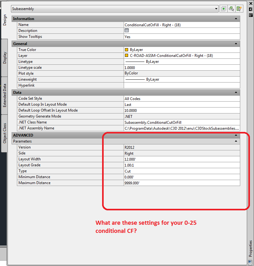
version 2013
Side Right
Layout Width 25.00'
Layout Grade 5.00:1
Min Distance 0'
Max. Distance 25.00'
Side Right
Layout Width 25.00'
Layout Grade 5.00:1
Min Distance 0'
Max. Distance 25.00'
JBozz300 Out!
C3D 2014 SP1
i7-3770 @ 3.40
16 GB - Win 7 Pro-64 SP1
NVidia Quadro 2000
C3D 2014 SP1
i7-3770 @ 3.40
16 GB - Win 7 Pro-64 SP1
NVidia Quadro 2000
Message 6 of 19
03-12-2014
12:46 PM
- Mark as New
- Bookmark
- Subscribe
- Mute
- Subscribe to RSS Feed
- Permalink
- Report
03-12-2014
12:46 PM
And does it say Cut or Fill?
One thing that you might try is to change layout width to 30 and see what happens. All the examples I've seen have this number much larger than the Max Width -- I'm not sure why but I'm game if you are.
My duh! The image SAYS fill. That answers that.
Don Ireland
Engineering Design Technician![]()
If a reply solves your issue, please remember to click on "Accept as Solution". This will help other users looking to solve a similar issue. Thank you.
Please do not send a PM asking for assistance. That's what the forums are for. This allows everyone to benefit from the question asked and the answers given.
Message 7 of 19
03-12-2014
01:02 PM
- Mark as New
- Bookmark
- Subscribe
- Mute
- Subscribe to RSS Feed
- Permalink
- Report
03-12-2014
01:02 PM
The problem with that is if I reduce it down to say 10' it stills runs out as far as it needs to tie into the surface.
JBozz300 Out!
C3D 2014 SP1
i7-3770 @ 3.40
16 GB - Win 7 Pro-64 SP1
NVidia Quadro 2000
C3D 2014 SP1
i7-3770 @ 3.40
16 GB - Win 7 Pro-64 SP1
NVidia Quadro 2000
Message 8 of 19
03-12-2014
01:17 PM
- Mark as New
- Bookmark
- Subscribe
- Mute
- Subscribe to RSS Feed
- Permalink
- Report
03-12-2014
01:17 PM
Any ideas why the initial condition (0-25) is going past the 25' and not allowing the second condition to take effect?
Yes, beacuse Layout Grade and Layout Width have no effect regarding the corridor model.
Fred Ernst, PE
C3D 2025
Ernst Engineering
www.ernstengineering.com
Message 9 of 19
03-12-2014
01:29 PM
- Mark as New
- Bookmark
- Subscribe
- Mute
- Subscribe to RSS Feed
- Permalink
- Report
03-12-2014
01:29 PM
Still doesn't answer the question. I know that the layout grade and width has nothing to do with what it actually does. The settings for the max offset is set to 25', yet it still runs past the 25' limit. Like posted before I changed it to 10' as the max and it still run 40-50' and tied into the surface.
JBozz300 Out!
C3D 2014 SP1
i7-3770 @ 3.40
16 GB - Win 7 Pro-64 SP1
NVidia Quadro 2000
C3D 2014 SP1
i7-3770 @ 3.40
16 GB - Win 7 Pro-64 SP1
NVidia Quadro 2000
Message 10 of 19
03-12-2014
01:30 PM
- Mark as New
- Bookmark
- Subscribe
- Mute
- Subscribe to RSS Feed
- Permalink
- Report
03-12-2014
01:30 PM
fcernst wrote:
Any ideas why the initial condition (0-25) is going past the 25' and not allowing the second condition to take effect?
Yes, beacuse Layout Grade and Layout Width have no effect regarding the corridor model.
I was just getting ready to say that I just re-read up on conditional SA. It's been a while since I used them.
Layout Width
Specifies the grade of the line that is drawn to represent this subassembly in
layout mode. This parameter, in combination with the Layout Width parameter,
allows you to position the ConditionalCutOrFill subassembly and subassemblies
that are attached to it, but does not display or have any effect in the corridor
model.
Layout Grade
Specifies the grade of the line that is drawn to represent this subassembly in
layout mode. This parameter, in combination with the Layout Width parameter,
allows you to position the ConditionalCutOrFill subassembly and subassemblies
that are attached to it, but does not display or have any effect in the corridor
model.
The max refers to how high above or below the point the existing ground is.
Don Ireland
Engineering Design Technician![]()
If a reply solves your issue, please remember to click on "Accept as Solution". This will help other users looking to solve a similar issue. Thank you.
Please do not send a PM asking for assistance. That's what the forums are for. This allows everyone to benefit from the question asked and the answers given.
Message 11 of 19
03-12-2014
01:34 PM
- Mark as New
- Bookmark
- Subscribe
- Mute
- Subscribe to RSS Feed
- Permalink
- Report
03-12-2014
01:34 PM
It sounds like you might be better off using a custom SA. You can set one up that will accept a min and max WIDTH then if you can hit the surface within that range using a specified slope, then do so --otherwise use the alternate slope.
Don Ireland
Engineering Design Technician![]()
If a reply solves your issue, please remember to click on "Accept as Solution". This will help other users looking to solve a similar issue. Thank you.
Please do not send a PM asking for assistance. That's what the forums are for. This allows everyone to benefit from the question asked and the answers given.
Message 12 of 19
03-12-2014
02:22 PM
- Mark as New
- Bookmark
- Subscribe
- Mute
- Subscribe to RSS Feed
- Permalink
- Report
03-12-2014
02:22 PM
I guess in my case that makes no sense to use a condition subassembly based off of depth at any point as opposed to a horizontal offset. That's where I messed up; I thought that the min-max distance was a horizontal distance that the condition would run from the origin (EOP) then would change to the other condition if not met.
JBozz300 Out!
C3D 2014 SP1
i7-3770 @ 3.40
16 GB - Win 7 Pro-64 SP1
NVidia Quadro 2000
C3D 2014 SP1
i7-3770 @ 3.40
16 GB - Win 7 Pro-64 SP1
NVidia Quadro 2000
Message 13 of 19
03-13-2014
05:45 AM
- Mark as New
- Bookmark
- Subscribe
- Mute
- Subscribe to RSS Feed
- Permalink
- Report
03-13-2014
05:45 AM
You can still use the ConditionalCutFill subassembly to test whether you are in cut or fill at the 25' offset mark, then proceed accordingly:


Fred Ernst, PE
C3D 2025
Ernst Engineering
www.ernstengineering.com
Message 14 of 19
03-13-2014
07:57 AM
- Mark as New
- Bookmark
- Subscribe
- Mute
- Subscribe to RSS Feed
- Permalink
- Report
03-13-2014
07:57 AM
Use generic link subassemblies to shift the conditional test location 25 feet. Test to see ff the depth is greater than 1.25 (25' x 5%). Then on the end of each condition, use generic links to return back 25'.
Read more here: http://forums.autodesk.com/t5/AutoCAD-Civil-3D-General/Comparison-point-on-conditional-subassemblies...
David Zavislan, P.E. | Wood Rodgers, Inc.
Message 15 of 19
03-14-2014
03:27 PM
- Mark as New
- Bookmark
- Subscribe
- Mute
- Subscribe to RSS Feed
- Permalink
- Report
03-14-2014
03:27 PM
One scenario that simply testing for cut or fill at 25' @ 5% like I suggested with a ConditionalCutFill SA would fail at, would be if you had a hump in between that you did not want to grade out through, and you were in fill at the 25' offset test point.

Fred Ernst, PE
C3D 2025
Ernst Engineering
www.ernstengineering.com
Message 16 of 19
03-14-2014
08:08 PM
- Mark as New
- Bookmark
- Subscribe
- Mute
- Subscribe to RSS Feed
- Permalink
- Report
03-14-2014
08:08 PM
Reading the original post I want to be sure that I understand the intent. Starting from the shoulder the section extends outward at -5% until it daylights or reaches 25' from EOP. If it reaches the 25' without daylighting, then it continues at -3% until it daylights, or falls of the edge of the surface.
This is DaylightGeneral. With the Fill1 link is set to -20:1 for 25' and the Flat fill slope set to -33.333/1 it should perform as shown below.


Steve
Please use the Accept as Solution or Kudo buttons when appropriate
Steve
Expert Elite Alumnus
Expert Elite Alumnus
Message 17 of 19
03-15-2014
07:31 AM
- Mark as New
- Bookmark
- Subscribe
- Mute
- Subscribe to RSS Feed
- Permalink
- Report
03-15-2014
07:31 AM
I can confirm.
I didn't realize DaylightGeneral had this initial Fill Width funtionality for this problem (Kudos given). This will solve that hump scenario where the cut/fill test at 25' would fail.


Fred Ernst, PE
C3D 2025
Ernst Engineering
www.ernstengineering.com
Message 18 of 19
03-20-2014
06:53 AM
- Mark as New
- Bookmark
- Subscribe
- Mute
- Subscribe to RSS Feed
- Permalink
- Report
03-20-2014
06:53 AM
I did not try this last scenario and will need to give it a try. I ended up creating a new baseline along the EOP and running out the -5% to determine where it went past the 25' offset. In the areas that went past it I just created a different assembly that went to the 25', then matched from there at the -3%. For the most part, the areas that went past were confined to 2 long areas and so it was pretty easy to designate the regions. This also allows me to basically let the pavement on the runway to be independent so-to-speak from the infield area as they usually need some additional contour tweeking. Thanks for all of the help guys......
JBozz300 Out!
C3D 2014 SP1
i7-3770 @ 3.40
16 GB - Win 7 Pro-64 SP1
NVidia Quadro 2000
C3D 2014 SP1
i7-3770 @ 3.40
16 GB - Win 7 Pro-64 SP1
NVidia Quadro 2000
Message 19 of 19
03-20-2014
08:53 AM
- Mark as New
- Bookmark
- Subscribe
- Mute
- Subscribe to RSS Feed
- Permalink
- Report
03-20-2014
08:53 AM
Boon's suggestion automates all of this and is easy to set up.
I never use DaylightGeneral because it doesn't have capability to target horizontal and elevation targets which we always need to tie ditches into culverts and bridges.
However it works perfectly for your Fill problem, and I will consider using it for more Fill scenarios now.
Fred Ernst, PE
C3D 2025
Ernst Engineering
www.ernstengineering.com
Reply
Topic Options
- Subscribe to RSS Feed
- Mark Topic as New
- Mark Topic as Read
- Float this Topic for Current User
- Bookmark
- Subscribe
- Printer Friendly Page
Forums Links
Can't find what you're looking for? Ask the community or share your knowledge.
Post to forums

