Community
- Forums Home
- >
- Civil 3D Community
- >
- Civil 3D Forum
- >
- Re: Pipe in Profile going in the wrong direction
Civil 3D Forum
Welcome to Autodesk’s Civil 3D Forums. Share your knowledge, ask questions, and explore popular AutoCAD Civil 3D topics.
Turn on suggestions
Auto-suggest helps you quickly narrow down your search results by suggesting possible matches as you type.
Reply
Topic Options
- Subscribe to RSS Feed
- Mark Topic as New
- Mark Topic as Read
- Float this Topic for Current User
- Bookmark
- Subscribe
- Printer Friendly Page
Message 1 of 14
11-09-2012
11:50 AM
- Mark as New
- Bookmark
- Subscribe
- Mute
- Subscribe to RSS Feed
- Permalink
- Report
11-09-2012
11:50 AM
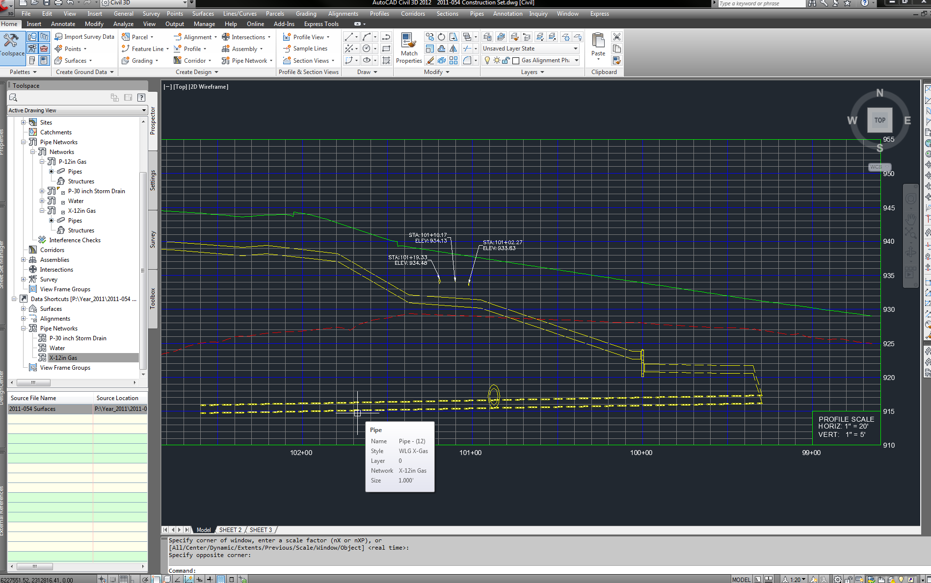
I have the following situation:
I have a pipe network (data shortcut) showing in the profile.
The pipe network was designed from station 98+65 to 100+00.
But the first pipe (from station 98+65 to 99+30) is shown going from station 99+30 to 102+60.
The pipe has a lenght of about 65' and some how it is being projected incorrectly.
Any ideas why its going in the wrong direction?
The profile is shown going from right to left.
See attached image.
Thanks for your help.
Windows 7 64-bit
Civil 3D 2012 SP2
Solved! Go to Solution.
Solved by bruce.jordan. Go to Solution.
13 REPLIES 13
Message 2 of 14
11-09-2012
12:36 PM
- Mark as New
- Bookmark
- Subscribe
- Mute
- Subscribe to RSS Feed
- Permalink
- Report
11-09-2012
12:36 PM
Is there a curve in the alignment? Is it possible that one end of the pipe is being projected to the wrong part of the alignment, but still perpendicularly projected? I'd be interested in a screen shot of the plan.
Mark Green
Working on Civil 3D in Canada![]()
Message 3 of 14
11-09-2012
01:30 PM
- Mark as New
- Bookmark
- Subscribe
- Mute
- Subscribe to RSS Feed
- Permalink
- Report
11-09-2012
01:30 PM
There are no curves in the alignment.
Attached is a plan and profile.
Message 4 of 14
11-09-2012
01:35 PM
- Mark as New
- Bookmark
- Subscribe
- Mute
- Subscribe to RSS Feed
- Permalink
- Report
11-09-2012
01:35 PM
I didn't really mean just curves; I mean any PIs, bends.
I'm having a hard time with that plan, any chance you can turn off some layers and take a screenshot with just the alignment and the pipes?
Mark Green
Working on Civil 3D in Canada![]()
Message 5 of 14
11-09-2012
01:49 PM
- Mark as New
- Bookmark
- Subscribe
- Mute
- Subscribe to RSS Feed
- Permalink
- Report
11-09-2012
01:49 PM
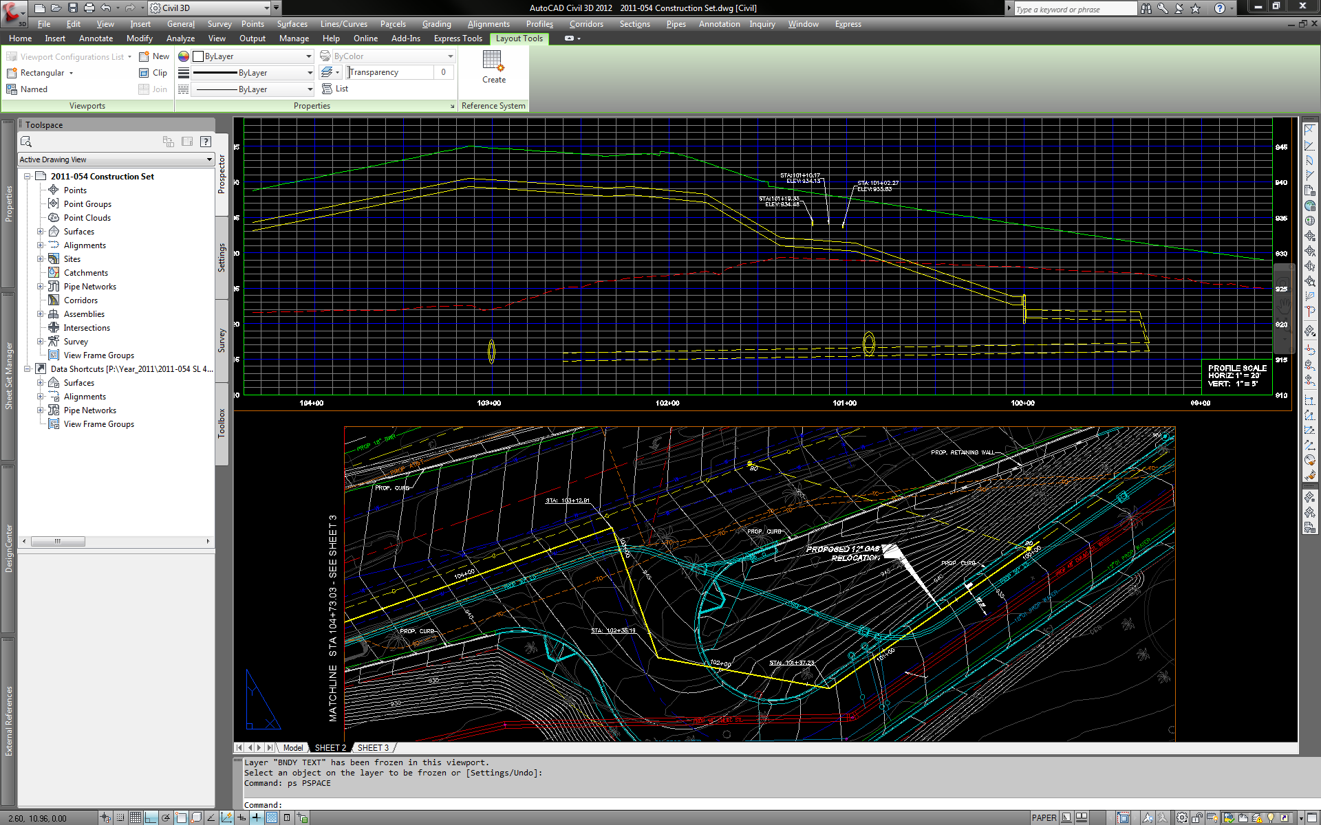
There are PI's and vertical bends.
I hope the attched image makes it clearer to understand.
Message 6 of 14
11-09-2012
01:54 PM
- Mark as New
- Bookmark
- Subscribe
- Mute
- Subscribe to RSS Feed
- Permalink
- Report
11-09-2012
01:54 PM
In your plan view (pipe profile 2.png), it appears their is a pipe network going up to the Northwest (assuming north is up) starting at 100+00.
If I look at the NW end of that pipe, it would project perp to around 102+00 which corresponds to your profile view.
Did you project the correct pipe onto profile?
Also, if I may make a performance recommendation in case you have not run across it - I noticed in your first image that when you select an object you get sort of a dashed line highlight - if you change your previeweffect = 1, it will just use a thickended line sometimes drastically improving performance since it does not have to generate the dashing.
-Bruce
Message 7 of 14
11-09-2012
02:08 PM
- Mark as New
- Bookmark
- Subscribe
- Mute
- Subscribe to RSS Feed
- Permalink
- Report
11-09-2012
02:08 PM
On 'pipe profile 2.png' it does show an existing pipe going NW but you will notice that is does not show on 'pipe profile 3.png' becuase is not part of the pipe network.
I show two different pipe networks.
The dashed represent the existing pipe and the continuous represent the proosed pipe.
I suspect that the profile from station 99+30 to 102+60 is projecting the existing pipe network perpendicular to it.
Is there a way for it not to do that?
Regarding performance, I will give it a try.
Thanks
Message 8 of 14
11-09-2012
02:10 PM
- Mark as New
- Bookmark
- Subscribe
- Mute
- Subscribe to RSS Feed
- Permalink
- Report
11-09-2012
02:10 PM
I'm still having a hard time seeing what's what.
In your plan, draw a line from your alignment at the station where the end of the pipe is being drawn to, to the actual end of the pipe. See if that makes it any clearer why it is picking that station.
Mark Green
Working on Civil 3D in Canada![]()
Message 9 of 14
11-09-2012
02:20 PM
- Mark as New
- Bookmark
- Subscribe
- Mute
- Subscribe to RSS Feed
- Permalink
- Report
11-09-2012
02:20 PM
hosegueda -
In the Profile, can you check your pipe properties (highlight pipe and right-click selecting PIPE PROPERTEIS) of the pipe in question and just verify that the NAME IS what you expect.
Also, highlight and right-click on your PROFILE GRID and select profile view properties - there is a PIPE NETWORK tab.
Verify that the pipes you want to show have the DRAW column checked on, and those you do not want to show are unchecked.
-Bruce
Message 10 of 14
11-09-2012
02:29 PM
- Mark as New
- Bookmark
- Subscribe
- Mute
- Subscribe to RSS Feed
- Permalink
- Report
11-09-2012
02:29 PM
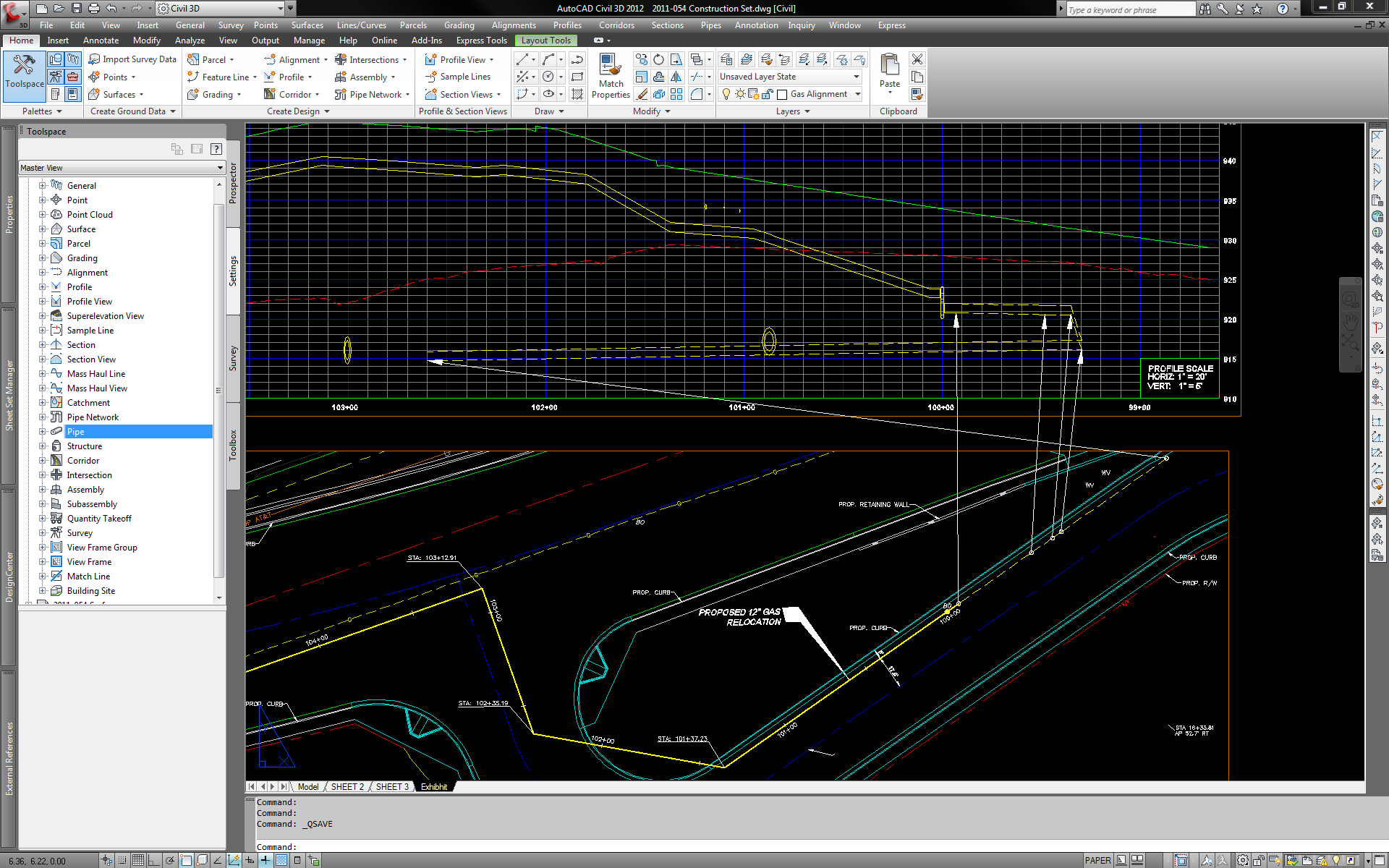
Here is another image with arrows pointing to where the pipe is in relation to plan and profile.
The pipe is the correct one shown in profile when I click on PIPE PROPERTIES.
And under PIPE NETWORK tab, I have the pipe checked to show on profile.
Message 11 of 14
11-09-2012
02:41 PM
- Mark as New
- Bookmark
- Subscribe
- Mute
- Subscribe to RSS Feed
- Permalink
- Report
11-09-2012
02:41 PM
Ah, that really made it obvious what it is doing.
And just to verify, your alignment goes to at least the NE end of your pipe network (including rounding errors)?
I don't see any labeling before station 100+00.
-Bruce
Message 12 of 14
11-09-2012
02:49 PM
- Mark as New
- Bookmark
- Subscribe
- Mute
- Subscribe to RSS Feed
- Permalink
- Report
11-09-2012
02:49 PM
Yes the pipe goes to the NE. Should I extend the alignment to go further?
The orignal plan was done in LDD and the alignment only went to station 100+00.
I extended it to include the existing pipe.
I don't show the station labels for the entire alignment.
Message 13 of 14
11-09-2012
02:52 PM
- Mark as New
- Bookmark
- Subscribe
- Mute
- Subscribe to RSS Feed
- Permalink
- Report
11-09-2012
02:52 PM
I'd say to rule out the alignment being too short, extend it say 10' past the NE end.
If it's too short, you will get the results you are showing in your images.
-Bruce
Message 14 of 14
11-09-2012
03:01 PM
- Mark as New
- Bookmark
- Subscribe
- Mute
- Subscribe to RSS Feed
- Permalink
- Report
11-09-2012
03:01 PM
Problem solved!
I extended the alignment further and it works now.
The pipe and alignment were off by 0.0045
See image.
Thanks for your help.
Reply
Topic Options
- Subscribe to RSS Feed
- Mark Topic as New
- Mark Topic as Read
- Float this Topic for Current User
- Bookmark
- Subscribe
- Printer Friendly Page

