Community
Civil 3D Forum
Welcome to Autodesk’s Civil 3D Forums. Share your knowledge, ask questions, and explore popular AutoCAD Civil 3D topics.
Turn on suggestions
Auto-suggest helps you quickly narrow down your search results by suggesting possible matches as you type.
Reply
Topic Options
- Subscribe to RSS Feed
- Mark Topic as New
- Mark Topic as Read
- Float this Topic for Current User
- Bookmark
- Subscribe
- Printer Friendly Page
- « Previous
-
- 1
- 2
- Next »
Message 1 of 24
Anonymous
1880 Views, 23 Replies
01-20-2013
07:31 AM
- Mark as New
- Bookmark
- Subscribe
- Mute
- Subscribe to RSS Feed
- Permalink
- Report
01-20-2013
07:31 AM
Iterating height levels for a polyline
I have a problem iterating heights when making a polyline between two different points that have Z-values. I've used Autocad Civil 3D for working with geodedic data with height measurements before and I remember using geodetically measured height values, transforming them into a surface and then when I create a 3Dpolyline within this area the polyline automatically gets z-values that change along the line. In other words, I could use this 3Dpolyline to obtain a profile that gives me z-values even where there is no exact point with a value has been physically measured. It was a while ago I worked with Autocad and now when I started again I have a similar problem but can't manage to create a surface and get iterated values.
My exact problem this time is:
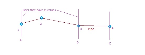
I have a sewage pipe that runs for several kilometers that is drawn as a 3Dpolyline, with correct x- and y-values. It doesn't have any z-values yet and these are what I want to obtain. I want the polyline to have continous z-values that changes along the polyline (not only in vertexes) so that a smooth profile can be drawn if wanted. I have data of measured actual z-values for approximately every 500 meters or so along the sewage pipe and these are currently drawn as 3Dpolylines of around 20 meters going perpendicular to the pipe (as in the picture). In other words there are bars with z-values crossing the pipe all along the stretch. Now, what I want to do is to somehow make the polyline that represent the pipe to get the hights from these perpendicular bars with the measured z-values. If I try to draw a new 3Dpolyline between two of the measured bars where the actual pipe is supposed to be, the end vertexes of the 3Dpolyline gets the z-values of the bars. However, the value inbetween the bars gets the Z-value 0. So, if I start a 3Dpoly on bar 1 then continue the pipe with another vertex, and then finish off at the second bar I will have 2 vertexes with the correct z-value but the middle vertex will be incorrect (0). How do I get the pipe to get the correct zvalues automatically iterated from the values on the crossing bars? Is this even possible to do? Should I create a surface from the bars first, and in that case how do I do that? If possible I don't only want the vertexes between bars to have iterated z-values, I also want the entire line to have a correct value.
I've attatched a crappy image made in paint (since I don't have Autocad on my home PC, only at the office). And just to make things even clearer I'll give an example. Let's say the pipe distance from 1 to 2 is 10 meters, the distance between 1 to 3 is 30 meters and the z-values of bar A and bar B is 10 and 25 respecitvely. So, when I draw a 3Dpolyline from 1 to 4, I want the vertex 2 to automatically get z-value 15 (since it's 1/3 on the way to B). In the same way, I would like for example the point on the pipe that is right in between 2 and 3 to have the z-value 20. I won't mind redoing the bars to for example singualar points instead, if that makes it all easier.
I'm really appreciating any help I can get with this! I get the feeling that it's easier than I belive it is to solve, and I feel that it should be possible. I just can't figure out how... =(
Sorry for the long description, I just wanted to make everything crystal clear 😃
Thanks!
23 REPLIES 23
Message 21 of 24
01-22-2013
12:45 AM
- Mark as New
- Bookmark
- Subscribe
- Mute
- Subscribe to RSS Feed
- Permalink
- Report
01-22-2013
12:45 AM
I'd reiterate that unless data is posted there's not a lot more that can be done - you don't appear to be doing anything incorrectly but it's always easier to be able to try it myself with actual "problem" data
neilyj (No connection with Autodesk other than using the products in the real world)
Did you find this post helpful? Feel free to Like this post.
Did your question get successfully answered? Then click on the ACCEPT SOLUTION button.
AEC Collection 2024 UKIE (mainly Civil 3D UKIE and IW)
Win 11 Pro x64, 1Tb Primary SSD, 1Tb Secondary SSD
64Gb RAM Intel(R) Xeon(R) W-11855M CPU @ 3.2GHz
NVIDIA RTX A5000 16Gb, Dual 27" Monitor, Dell Inspiron 7760
Message 22 of 24
01-22-2013
05:53 AM
- Mark as New
- Bookmark
- Subscribe
- Mute
- Subscribe to RSS Feed
- Permalink
- Report
01-22-2013
05:53 AM
@Anonymous wrote:They are regular lines.
Said in my best southern accent, "Well there's your problem right there!"
You can't add an AutoCAD line to a surface as breaklines. You have two options, convert them to polylines and then add them as breaklines or add them as drawing objects.
Message 23 of 24
01-22-2013
05:58 AM
- Mark as New
- Bookmark
- Subscribe
- Mute
- Subscribe to RSS Feed
- Permalink
- Report
01-22-2013
05:58 AM
Modify Panel > Add Data > Drawing Objects

neilyj (No connection with Autodesk other than using the products in the real world)
Did you find this post helpful? Feel free to Like this post.
Did your question get successfully answered? Then click on the ACCEPT SOLUTION button.
AEC Collection 2024 UKIE (mainly Civil 3D UKIE and IW)
Win 11 Pro x64, 1Tb Primary SSD, 1Tb Secondary SSD
64Gb RAM Intel(R) Xeon(R) W-11855M CPU @ 3.2GHz
NVIDIA RTX A5000 16Gb, Dual 27" Monitor, Dell Inspiron 7760
Message 24 of 24
01-23-2013
02:07 AM
- Mark as New
- Bookmark
- Subscribe
- Mute
- Subscribe to RSS Feed
- Permalink
- Report
01-23-2013
02:07 AM
Hi again!
Converting the lines to polylines didn't change anything. I still can't produce a surface. To be able to illustrate this to you guys, I made a new version of the original dwg file I'm working with, just copying a small segment consisting of 3 bars of the entire water pipe in question. I created a new file and used the copy with base point command from my original file to the new one. What is really strange is that in this new file it works perfectly fine to create a surface as in Brians video! And that is despite the fact that 2 of the bars are lines and 1 is a polyline. So, it seems like it's ok to use lines as well as polylines for breaklines and it's no problem to mix them as you like. Still, when I attempt the exact same method in my original file, trying with the exact 3 bars that I copied and that worked perfectly fine in the new file, I get no surface! I add breaklines, select the lines but nothing happens! Seriousely, what is this all about? Could it be that there's some function disabled in my orignial file, so I can't make surfaces? This is just driving me crazy... I guess I could copy all of my original file to make a new one - but it's annoying to give up without knowing what the reason for the problem was! Sadly I can't post the original file since it's from work...
- « Previous
-
- 1
- 2
- Next »
Reply
Topic Options
- Subscribe to RSS Feed
- Mark Topic as New
- Mark Topic as Read
- Float this Topic for Current User
- Bookmark
- Subscribe
- Printer Friendly Page
- « Previous
-
- 1
- 2
- Next »

