Community
Civil 3D Forum
Welcome to Autodesk’s Civil 3D Forums. Share your knowledge, ask questions, and explore popular AutoCAD Civil 3D topics.
Turn on suggestions
Auto-suggest helps you quickly narrow down your search results by suggesting possible matches as you type.
Reply
Topic Options
- Subscribe to RSS Feed
- Mark Topic as New
- Mark Topic as Read
- Float this Topic for Current User
- Bookmark
- Subscribe
- Printer Friendly Page
Message 1 of 11
05-04-2011
08:00 AM
- Mark as New
- Bookmark
- Subscribe
- Mute
- Subscribe to RSS Feed
- Permalink
- Report
05-04-2011
08:00 AM
Intersection Design/90 degree turn
Can anyone give me some advice on an intersection like the one I've attached. I've tried a couple of things but am hoping for an easier solution.
Using Civil 3D 2012.
Lisa
Windows 10 Pro x 64 bit
Intel Xeon CPU @ 3.8 GHz
32 GB RAM
NVIDIA Quadro P2200
Civil 3D 2020
Windows 10 Pro x 64 bit
Intel Xeon CPU @ 3.8 GHz
32 GB RAM
NVIDIA Quadro P2200
Civil 3D 2020
10 REPLIES 10
Message 2 of 11
05-04-2011
03:17 PM
- Mark as New
- Bookmark
- Subscribe
- Mute
- Subscribe to RSS Feed
- Permalink
- Report
05-04-2011
03:17 PM
For an intersection, you have to have at least a "tee" so you would need to basically have two separate alignments, and have one continue past the other for about 25 to 50'.
If you are just wanting to make a turn like you show, put a curve in your alignment that follows the inside curb return, then have your outside lane target the squared-up portion of the road.For modelling purposes, having a sharp break in your alignment does not work out well because there is no was to have a cross section cover the outside corner.
In fact, I recently had to model something almost exactly the same as what you are trying to do. I'll attach a screenshot of what I'm describing.
Message 3 of 11
05-04-2011
03:23 PM
- Mark as New
- Bookmark
- Subscribe
- Mute
- Subscribe to RSS Feed
- Permalink
- Report
05-04-2011
03:23 PM
Thanks for the information. This is for a Taxiway for and Airport so there are some issues with how we make the corner. We usually don't put a curve in the centerline so I'll have to find out if it's acceptable to do that.
Lisa
Windows 10 Pro x 64 bit
Intel Xeon CPU @ 3.8 GHz
32 GB RAM
NVIDIA Quadro P2200
Civil 3D 2020
Windows 10 Pro x 64 bit
Intel Xeon CPU @ 3.8 GHz
32 GB RAM
NVIDIA Quadro P2200
Civil 3D 2020
Message 4 of 11
05-04-2011
03:39 PM
- Mark as New
- Bookmark
- Subscribe
- Mute
- Subscribe to RSS Feed
- Permalink
- Report
05-04-2011
03:39 PM
Ah, OK. To do it without a curve in your centerline, you'd have to come off the outside alignments and target the centerline. It would be similar to the process of doing a cul-de-sac in that regard.
If you can do it with the curve in the centerline, though, I have found that method to be much easier. If you need the crown of the road to follow the straight-line and then make the sharp 90d turn, you could create an alignment to target and model the crown that way with a little bit of assembly trickery.
Either way you do it, there's no way to do it with the existing intersection tools in C3D. I wish there was - this was one of the first issues I ran into when I switched from LDT.
Message 5 of 11
05-04-2011
08:47 PM
- Mark as New
- Bookmark
- Subscribe
- Mute
- Subscribe to RSS Feed
- Permalink
- Report
05-04-2011
08:47 PM
...I see so many posts about appraches to these types of Intersecstion situations here on the DG. All of which require doing it with a corridor. Let me share a different approach if I may. I handle 95% of my intersection situations/surfaces with Feature Lines and Grading Groups. In your case I see three feature lnes and two Grading Groups. Yes , the caveat to this method is I can't pull Material Quantities etc. But, the time its takes me to set up all these additional Alignments, Profiles and Assemblies is to lengthy and requires some serous drawing Management. With that said have you ever considered handling these intersections with this approach? I find it much qucker/faster and a lot less drawing Management with respect to Alignments, Profiles etc. For example...North South Corridor (end at Curb Return) = Surface1, East West Corridor (end at Curb Return) = Surface 2, Intersection Surface (Curb Returns, CL, ETW and Daylights) = Surface 3. Then Create a FG Composite Surface and Paste Surfaces 1, 2 and 3 in that order. This has worked great for me.
Regards,
K
Message 6 of 11
05-05-2011
01:02 PM
- Mark as New
- Bookmark
- Subscribe
- Mute
- Subscribe to RSS Feed
- Permalink
- Report
05-05-2011
01:02 PM
I kind of figured I would have to make alignments to grade to or use grading objects instead of corridors. We are currently using LDT and I am evaluating C3D 2012 to see if we are going to be able to make the change this year. I have some experience with C3D so I'm glad that a lot of issues have been fixed/addressed in 2012 that I didn't like in previous versions. I will have to keep playing with it and see if we can make it work for what we want. Thanks for your help.
Lisa
Windows 10 Pro x 64 bit
Intel Xeon CPU @ 3.8 GHz
32 GB RAM
NVIDIA Quadro P2200
Civil 3D 2020
Windows 10 Pro x 64 bit
Intel Xeon CPU @ 3.8 GHz
32 GB RAM
NVIDIA Quadro P2200
Civil 3D 2020
Message 7 of 11
05-05-2011
09:56 PM
- Mark as New
- Bookmark
- Subscribe
- Mute
- Subscribe to RSS Feed
- Permalink
- Report
05-05-2011
09:56 PM
It is possible without the outside curves, you just have to put very small arcs at the corners of your centreline alignment, and add a corridor frequency point to the midpoint of the arc.
My steps to create 90 degree bend in corridor.
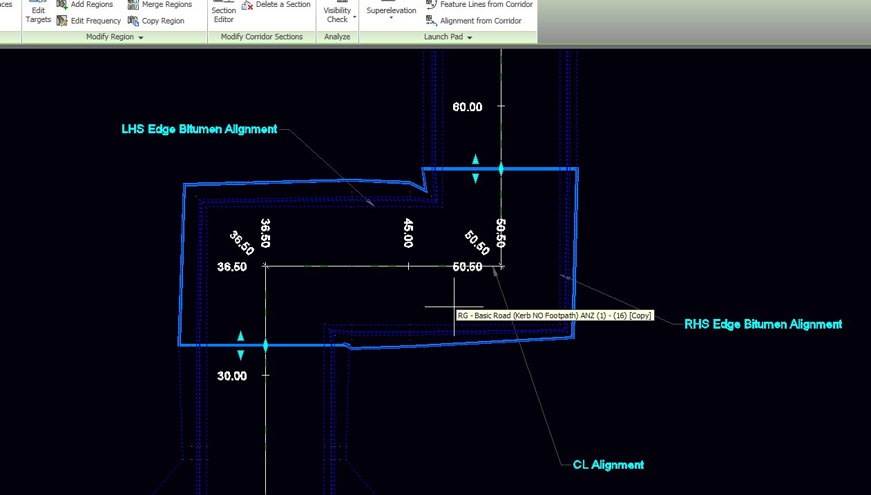
1. create the centreline with a polyline and offset either side to create edge polylines
2. convert the 3 polyline into alignments (in the attached screen captures the alignments are CL, LHS Edge Bitument, RHS Edge Bitumen.
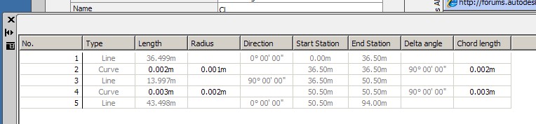
3. Create a 0.001 meter radius curve at each 90 deg bend on the centreline alignment
4. Create the profiles for the centreline.
5. Create a corridor using the Centreline Alignment
6. Target the lane edges to the outside alignments
7. Split the corridor, using the split region command, into seperate regions, one region to end before the inside corner, (split at 31.77 in the attached images), with the next region to end after the inside corner - as it relates to the centreline alignment. (about 41.6 in the attached images- except in the images i carried the region around past the next bend to end at 56.27)
8. In the corridor properties, set the frequency of the middle region, the one that goes around the bend, greater than the length of the region, and set the horizontal geometry point, superelevation critical points, profile geomtry points, profile high/low points and offset target geometry to No.
9. Add a frequency station to the corridor at the middle of the arc at the bend in the centreline alignment, (in the attached images, i added one at the middle of arcs for both bends in the alignment and one just after the first bend and one just before the second bend. giving me 4 frequency stations for the middle region)
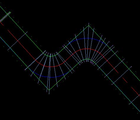
The corridor I created has a kerb and gutter with batter so at the corners, the corridor features outside the offset targets get narrowed due to the angle of the frequency line at the corner.
If you need a nicer look of featurelines on the inside of the bends beyond the offset targets, you can go into the corridor section editor and remove the subassemblies on the inside that would lie beyond the offset targets at the corner and have additional frequency stations closer to the inside corner.
I hope this is clear enough. If not I can do a video of the steps.
If a post provides a fix for your issue, click on "Accept as Solution" to help other users find solutions to problems they might have that are similar to yours.
Andrew Puller
Maitland, NSW, Australia
Windows 10 Enterprise 64bit
Intel core i7 11800 @ 2.30 GHz with 32GB Ram
Civil 3d 2023
Message 8 of 11
05-06-2011
06:51 AM
- Mark as New
- Bookmark
- Subscribe
- Mute
- Subscribe to RSS Feed
- Permalink
- Report
05-06-2011
06:51 AM
That sounds good, I'll give it a try today. Thanks!
Lisa
Windows 10 Pro x 64 bit
Intel Xeon CPU @ 3.8 GHz
32 GB RAM
NVIDIA Quadro P2200
Civil 3D 2020
Windows 10 Pro x 64 bit
Intel Xeon CPU @ 3.8 GHz
32 GB RAM
NVIDIA Quadro P2200
Civil 3D 2020
Message 9 of 11
05-06-2011
09:29 AM
- Mark as New
- Bookmark
- Subscribe
- Mute
- Subscribe to RSS Feed
- Permalink
- Report
05-06-2011
09:29 AM
Can you send a screen shot of your final corridor? I've attached what I'm getting. I'm not sure what I'm doing wrong. The squared off corner is rounded and the curb return looks like it's going the wrong way. My assembly is working for the straight sections. I've attached some screen shots, maybe you can see what is wrong.
Lisa
Windows 10 Pro x 64 bit
Intel Xeon CPU @ 3.8 GHz
32 GB RAM
NVIDIA Quadro P2200
Civil 3D 2020
Windows 10 Pro x 64 bit
Intel Xeon CPU @ 3.8 GHz
32 GB RAM
NVIDIA Quadro P2200
Civil 3D 2020
Message 10 of 11
05-07-2011
07:56 AM
- Mark as New
- Bookmark
- Subscribe
- Mute
- Subscribe to RSS Feed
- Permalink
- Report
05-07-2011
07:56 AM
From corridor.jpg, it looks like you have not set the horizontal geometry points to NO in the frequency settings dialogue. Compare your corridor to the Alignement properties and frequency settings.jpg picture from my previous post.
It also looks like the Edge of Pavement width targets have not been set. Are your lane subassemblies able to be widened to targets?
Attached is a drawing with a corridor set up as I described. If you take a look at that, you can check out the settings I used to make it work.
If a post provides a fix for your issue, click on "Accept as Solution" to help other users find solutions to problems they might have that are similar to yours.
Andrew Puller
Maitland, NSW, Australia
Windows 10 Enterprise 64bit
Intel core i7 11800 @ 2.30 GHz with 32GB Ram
Civil 3d 2023
Message 11 of 11
04-12-2016
10:52 AM
- Mark as New
- Bookmark
- Subscribe
- Mute
- Subscribe to RSS Feed
- Permalink
- Report
04-12-2016
10:52 AM
Well, We are at 2016 and looks like Autodesk didn't created a easy way to do 90º intersections.
Reply
Topic Options
- Subscribe to RSS Feed
- Mark Topic as New
- Mark Topic as Read
- Float this Topic for Current User
- Bookmark
- Subscribe
- Printer Friendly Page
Forums Links
Can't find what you're looking for? Ask the community or share your knowledge.
Post to forums

