Community
Civil 3D Forum
Welcome to Autodesk’s Civil 3D Forums. Share your knowledge, ask questions, and explore popular AutoCAD Civil 3D topics.
Turn on suggestions
Auto-suggest helps you quickly narrow down your search results by suggesting possible matches as you type.
Reply
Topic Options
- Subscribe to RSS Feed
- Mark Topic as New
- Mark Topic as Read
- Float this Topic for Current User
- Bookmark
- Subscribe
- Printer Friendly Page
Message 1 of 20
03-24-2010
07:58 AM
- Mark as New
- Bookmark
- Subscribe
- Mute
- Subscribe to RSS Feed
- Permalink
- Report
03-24-2010
07:58 AM
Converting DEM surface from meters to feet
I have DEM surface information that is all metric. I want to convert to imperial. I have changed the horizontal coordinate system to my local grid in feet, but I cannot figure out how to change the vertical surface from meters to feet. It should be a simple multiplication, but I cannot figure out how to perform any adjustment of the vertical elevations besides adding an offset.
19 REPLIES 19
Message 2 of 20
03-24-2010
12:56 PM
- Mark as New
- Bookmark
- Subscribe
- Mute
- Subscribe to RSS Feed
- Permalink
- Report
03-24-2010
12:56 PM
1. In drawing Toolspace
Settings > Drawing Settings > Units and Zone SETUP DRAWING COORDINATE SYSTEM ZONE AND UNITS
2.Settings > Surface Style
3.Prospector Tab
Surface > Create
Set Description
Set Style
4.Prospector Tab > Surfaces > Surface1 (+ EXPAND)
DEM > Add
Select DEM file (USGS ascii format)
Set CS Code
Set Null Elevation
OK
Note files in the DEM.SDTS.TARgz format can be converted to the USGS ascii format using MICRODEM (a free download from USNA)
Jim
MATRIX SURVEYS
Message 3 of 20
03-24-2010
09:24 PM
- Mark as New
- Bookmark
- Subscribe
- Mute
- Subscribe to RSS Feed
- Permalink
- Report
03-24-2010
09:24 PM
Thanks for your reply. This is a good description of how to import a DEM and convert the horizontal alignment. However, my problem is still the same. This process does not covert the vertical surface from meters to feet. The horizontal surface is correctly converted to feet, but the vertical remains in meters. BTW, the DEM I have is a GeoTIFF.
Message 4 of 20
03-25-2010
06:55 AM
- Mark as New
- Bookmark
- Subscribe
- Mute
- Subscribe to RSS Feed
- Permalink
- Report
03-25-2010
06:55 AM
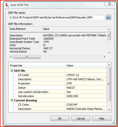
CS (coordinate system code has to be set in lower window) DEM insert screen
DEM files are usually in UTM NAD 27 METERS need to know the Projection (NAD 27 or NAD 83) and the Zone)
Wizard only works in same projection. Have to fill in the Systems in the lower Window for a transform.
Jim
DEM files are usually in UTM NAD 27 METERS need to know the Projection (NAD 27 or NAD 83) and the Zone)
Wizard only works in same projection. Have to fill in the Systems in the lower Window for a transform.
Jim
Message 5 of 20
03-25-2010
09:10 AM
- Mark as New
- Bookmark
- Subscribe
- Mute
- Subscribe to RSS Feed
- Permalink
- Report
03-25-2010
09:10 AM
This is interesting
When I create a new TIN surface, then set my GeoTIFF file as DEM input source, set the CS codes correctly and import, the horizontal projection is adjusted correctly, but it won't convert the vertical projection to feet. However, if I create a new Grid surface and select my GeoTIFF file as the DEM input source, I cannot select a CS code for the DEM file. I do notice that in the "DEM file information" area the coordinate system is being read from the file. When I go ahead and import the surface, the vertical is adjusted to feet, but the horizontal is not transformed.
PS
DEM files are not always in UTM NAD 27. I have to use what I have, which is Lat/Long NAD 83.
Message 6 of 20
04-27-2010
01:53 PM
- Mark as New
- Bookmark
- Subscribe
- Mute
- Subscribe to RSS Feed
- Permalink
- Report
04-27-2010
01:53 PM
Have you found a solution to this issue yet. I have run into the same problem, using the same data sources.
Message 7 of 20
04-27-2010
03:37 PM
- Mark as New
- Bookmark
- Subscribe
- Mute
- Subscribe to RSS Feed
- Permalink
- Report
04-27-2010
03:37 PM
No Autodesk solution. I found a program called Global Mapper that handles DEMs and images well, and it will convert meters to feet and change coordinate systems with little problem. It also merged and cropped my DEM. The only kicker is that it costs $350 to purchase. I haven't tried 2011 yet to see if they changed anything.
Message 8 of 20
09-13-2010
08:34 PM
- Mark as New
- Bookmark
- Subscribe
- Mute
- Subscribe to RSS Feed
- Permalink
- Report
09-13-2010
08:34 PM
Greetings! In Civil3d 2011, I started to play with the point cloud to take the ddf files to create surface. What I am curious to know is that the DEMs are in meters and I am looking to work in US feet...it would appear that if I have my drawing setup for the same zone and projection and I specify that the ddf are to be in the same format, does that mean that point clouding converts the meters into feet and places the file into the proper coordinate system? I am not sure if I need to make any adjustments or where to begin to verify that the information is good and viable to use for preliminary project work. Thanks! PS I did go through the tutorial and this was not addressed.
Infrastructure Design Suite 2012 - Premium, Intel Quad Core 2.66 Ghz, 8 GB Ram, Nvidia Quadro FX4800
Dilbert's Salary Theorem: Postulate 1: Knowledge is Power Postulate 2: Time is Money. Power = Work / Time. Since Knowledge = Power,
then Knowledge = Work / Time, and Tme = Money, then Knowledge = Work / Money. Solving for Money, we get: Money = Work / Knowledge.
Thus as Knowledge approaches zero, money approaches infinity, regardless of the amount of work done.
Message 9 of 20
09-14-2010
05:43 AM
- Mark as New
- Bookmark
- Subscribe
- Mute
- Subscribe to RSS Feed
- Permalink
- Report
09-14-2010
05:43 AM
I wrote a blog post on this topic a while back and I remember coming across an issue something like this. I believe the solution was to create a regular surface and add the DEM file to it. If you create a surface from a DEM file, things acted weird.
http://civil3dplus.wordpress.com/2010/02/02/using-dem-information-in-civil-3d/
Message 10 of 20
09-14-2010
07:08 AM
- Mark as New
- Bookmark
- Subscribe
- Mute
- Subscribe to RSS Feed
- Permalink
- Report
09-14-2010
07:08 AM
just a thought, what happens when i bring in the DEM in one dwg, then insert that dwg into a new dwg as a BLOCK, with a Z scale of 3.2808?
Message 11 of 20
09-14-2010
07:21 AM
- Mark as New
- Bookmark
- Subscribe
- Mute
- Subscribe to RSS Feed
- Permalink
- Report
09-14-2010
07:21 AM
never mind, just tested it myself, doesn't convert the verticals that way...
Message 12 of 20
09-14-2010
03:04 PM
- Mark as New
- Bookmark
- Subscribe
- Mute
- Subscribe to RSS Feed
- Permalink
- Report
09-14-2010
03:04 PM
Brain -
That was a great post and I was able to follow it. I did also read the comments from neilw in regards to seamless data and I could not find the DEMs as well. Perhaps if you could shed some light on how to extrapolate DEMS, that would be helpful as well especially if there is no difference between the NED 1" and a DEM.
Also, I wanted to see if your method would be duplicated by using point cloud and the boundaries line up beautifully between both methods. However, I am confused as to why the surface created by the point cloud would yield additional contours compared to creating a surface and importing the DEM directly into a surface yields fewer? Does the point cloud make additional assumptions than directly importing the DEM into a surface? Which would be more accurate (I know that is not the correct word)? When looking at the tutorial for point clouds, the purpose of the point cloud is to extrapolate elevations of objects from its surroundings. To me, the point cloud then in this case would yield a better representation of the surface in that regards. What are your thoughts?
PS I did make sure both surfaces were drawn using 20' minor and 100' major. That would be silly if I did not do that ![]()
Infrastructure Design Suite 2012 - Premium, Intel Quad Core 2.66 Ghz, 8 GB Ram, Nvidia Quadro FX4800
Dilbert's Salary Theorem: Postulate 1: Knowledge is Power Postulate 2: Time is Money. Power = Work / Time. Since Knowledge = Power,
then Knowledge = Work / Time, and Tme = Money, then Knowledge = Work / Money. Solving for Money, we get: Money = Work / Knowledge.
Thus as Knowledge approaches zero, money approaches infinity, regardless of the amount of work done.
Dilbert's Salary Theorem: Postulate 1: Knowledge is Power Postulate 2: Time is Money. Power = Work / Time. Since Knowledge = Power,
then Knowledge = Work / Time, and Tme = Money, then Knowledge = Work / Money. Solving for Money, we get: Money = Work / Knowledge.
Thus as Knowledge approaches zero, money approaches infinity, regardless of the amount of work done.
Message 13 of 20
09-14-2010
03:19 PM
- Mark as New
- Bookmark
- Subscribe
- Mute
- Subscribe to RSS Feed
- Permalink
- Report
09-14-2010
03:19 PM
Brian -
I went back to check out contours on the DEM that I imported because I know the area well. Doing your method was correct in terms of the vertical scale conversion from meters to feet however the surface created by the point cloud was a little over 3 times what the elevation should be for the same contour (not consistent like 3.27x, 3.125x, etc.). Have you ran into this as well?
Infrastructure Design Suite 2012 - Premium, Intel Quad Core 2.66 Ghz, 8 GB Ram, Nvidia Quadro FX4800
Dilbert's Salary Theorem: Postulate 1: Knowledge is Power Postulate 2: Time is Money. Power = Work / Time. Since Knowledge = Power,
then Knowledge = Work / Time, and Tme = Money, then Knowledge = Work / Money. Solving for Money, we get: Money = Work / Knowledge.
Thus as Knowledge approaches zero, money approaches infinity, regardless of the amount of work done.
Dilbert's Salary Theorem: Postulate 1: Knowledge is Power Postulate 2: Time is Money. Power = Work / Time. Since Knowledge = Power,
then Knowledge = Work / Time, and Tme = Money, then Knowledge = Work / Money. Solving for Money, we get: Money = Work / Knowledge.
Thus as Knowledge approaches zero, money approaches infinity, regardless of the amount of work done.
Message 14 of 20
09-14-2010
04:05 PM
- Mark as New
- Bookmark
- Subscribe
- Mute
- Subscribe to RSS Feed
- Permalink
- Report
09-14-2010
04:05 PM
Honestly, I haven't touched a DEM file since I wrote that blog post and I haven't had the chance to use the new point cloud tools in Civil 3D so I'm sorry I don't have an answer for you on that.
I am glad my blog was able to help you out though. It's nice to see it's worthwhile.
Message 15 of 20
02-15-2011
03:44 PM
- Mark as New
- Bookmark
- Subscribe
- Mute
- Subscribe to RSS Feed
- Permalink
- Report
02-15-2011
03:44 PM
Anyone found a solution to this. I too can't get the elevations to come in correct. Here is a screen cast of my problem [ http://screencast.com/t/D3Zd1VNuGxEG ]. As you will see my elevations should be around 30, but they come in at about 9.
Message 16 of 20
02-16-2011
05:52 AM
- Mark as New
- Bookmark
- Subscribe
- Mute
- Subscribe to RSS Feed
- Permalink
- Report
02-16-2011
05:52 AM
Hello,
I belive Brian had something posted earlier that may be helpful (first page). If that did not work for you you may want to try following blog post that explains in details what needs to be done and how: http://beingcivil.typepad.com/my_weblog/2011/02/import-metric-dem-file-into-imperial-drawing.html
Good luck!
Almas Suljevic
Product Support Specialist
Autodesk Global Subscription and Support
Autodesk, Inc.
Please click on "Accept as Solution" if post helped you resolve the issue.
Message 17 of 20
02-16-2011
06:52 AM
- Mark as New
- Bookmark
- Subscribe
- Mute
- Subscribe to RSS Feed
- Permalink
- Report
02-16-2011
06:52 AM
Thanks for the post. Yes that works...but wow what a work around. For a big surface this takes forever. However, this is a valid work arouind.
Message 18 of 20
04-04-2012
04:30 PM
- Mark as New
- Bookmark
- Subscribe
- Mute
- Subscribe to RSS Feed
- Permalink
- Report
04-04-2012
04:30 PM
I've found that it doesn't look like you can change the coordinate system, but if you pick where the elipses dots should be they appear and you can then select the coordinate system.
HTH
Matt
Message 19 of 20
04-21-2016
08:05 AM
- Mark as New
- Bookmark
- Subscribe
- Mute
- Subscribe to RSS Feed
- Permalink
- Report
04-21-2016
08:05 AM
If you extracted 3d faces from the surface then rescaling a block insert would give you the geometry to create a new surface with the correct elevation units.
Message 20 of 20
01-22-2024
07:43 AM
- Mark as New
- Bookmark
- Subscribe
- Mute
- Subscribe to RSS Feed
- Permalink
- Report
01-22-2024
07:43 AM
Thanks for that blog. Setting the DEM file settings in the dialog box was indeed the one part I was missing. Metric to Imperial is some steps. Open Civil 3d metric. The DEM file I downloaded (a geotiff) had missing information attached to it. I had to go to the website I downloaded from (for me MASSGIS) and read up how the file was created to get the correct georeference data. Some info was also extracted from the auxiliary html files I had with the download. After I input the correct info in the "add DEM data" dialog box, everything came in correctly. I then exported that surface using LandXMLout. Opened Civil3D Imperial then used LandXMLin to bring info into feet. Thank you.
Reply
Topic Options
- Subscribe to RSS Feed
- Mark Topic as New
- Mark Topic as Read
- Float this Topic for Current User
- Bookmark
- Subscribe
- Printer Friendly Page

