Community
- Forums Home
- >
- AutoCAD Architecture Community
- >
- AutoCAD Architecture Forum
- >
- AEC Walls showing as single lines (not showing up correctly)
AutoCAD Architecture Forum
Welcome to Autodesk’s AutoCAD Architecture Forums. Share your knowledge, ask questions, and explore popular AutoCAD Architecture topics.
Turn on suggestions
Auto-suggest helps you quickly narrow down your search results by suggesting possible matches as you type.
AEC Walls showing as single lines (not showing up correctly)
21 REPLIES 21
Reply
Topic Options
- Subscribe to RSS Feed
- Mark Topic as New
- Mark Topic as Read
- Float this Topic for Current User
- Bookmark
- Subscribe
- Printer Friendly Page
Message 1 of 22
Anonymous
4451 Views, 21 Replies
06-29-2012
06:15 AM
- Mark as New
- Bookmark
- Subscribe
- Mute
- Subscribe to RSS Feed
- Permalink
- Report
06-29-2012
06:15 AM
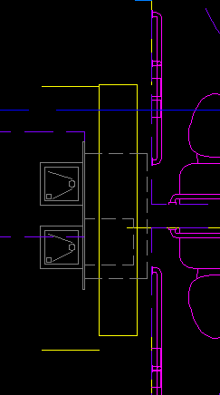
AEC Walls showing as single lines (not showing up correctly)
We recently upgraded to AutoCAD Architecture 2013 ![]() from Architecture 2011
from Architecture 2011 ![]() and am having all sorts of intermittent issues with walls showing up as single lines in x-refs (even though the file being refrenced has been brought into 2013 and shows correctly when opened by itself). We are also having intermittent issues with the plans and walls themselfs showing as a single line. I need assistance on strightening this out as we have several jobs pending construction that are all having this issue in incosestant areas.
and am having all sorts of intermittent issues with walls showing up as single lines in x-refs (even though the file being refrenced has been brought into 2013 and shows correctly when opened by itself). We are also having intermittent issues with the plans and walls themselfs showing as a single line. I need assistance on strightening this out as we have several jobs pending construction that are all having this issue in incosestant areas.
Additional Info: Windows XP Pro - 32 Bit
Thanks!
Nick
21 REPLIES 21
Message 2 of 22
06-29-2012
08:57 AM
- Mark as New
- Bookmark
- Subscribe
- Mute
- Subscribe to RSS Feed
- Permalink
- Report
06-29-2012
08:57 AM
Check out your Display Configuration in the problem drawing. From your image it looks to me like it is set to Diagnostic which shows walls as single line.
~ Mary
Message 3 of 22
06-29-2012
09:41 AM
- Mark as New
- Bookmark
- Subscribe
- Mute
- Subscribe to RSS Feed
- Permalink
- Report
Message 4 of 22
06-29-2012
10:23 AM
- Mark as New
- Bookmark
- Subscribe
- Mute
- Subscribe to RSS Feed
- Permalink
- Report
06-29-2012
10:23 AM
The Display Configuration Pick List is at the bottom right of the screen within the 'Drawing Status Bar' between the Annotation Scale pick list and Cut Plane. ~ Mary
Message 5 of 22
06-29-2012
11:18 AM
- Mark as New
- Bookmark
- Subscribe
- Mute
- Subscribe to RSS Feed
- Permalink
- Report
06-29-2012
11:18 AM
Also check the proper display configuration from the drop down box on the bottom right of your screen.
if set to 'Low Detail', all your walls will only show the shrinkwrap of the walls (single lines)
Message 6 of 22
07-02-2012
05:12 AM
- Mark as New
- Bookmark
- Subscribe
- Mute
- Subscribe to RSS Feed
- Permalink
- Report
Message 7 of 22
07-02-2012
08:33 AM
- Mark as New
- Bookmark
- Subscribe
- Mute
- Subscribe to RSS Feed
- Permalink
- Report
07-02-2012
08:33 AM
"Work" is not a standard OOTB Display Configuration (at least not in 2012), it may not be set to correctly show the walls. Is it a standard one for your company? If so is the person who set it up available to you? Have you changed it to one of the OOTB Display Configs to see if they work for you?
This is a somewhat difficult problem for the community to help you out with just through words... If you can, please post the drawing(s) so that we can look into the problem. BTW I don't have 2013 installed so someone else will have to help out.
~ Mary
Message 8 of 22
07-02-2012
09:12 AM
- Mark as New
- Bookmark
- Subscribe
- Mute
- Subscribe to RSS Feed
- Permalink
- Report
07-02-2012
09:12 AM
Are you using VisionREZ? "Work" is an OOTB VisionREZ display configuration.
Message 9 of 22
07-02-2012
09:27 AM
- Mark as New
- Bookmark
- Subscribe
- Mute
- Subscribe to RSS Feed
- Permalink
- Report
07-02-2012
09:27 AM
Or are you pehaps referring to "Model" and "Work" space? (Tabs located on the left bottom corner)
Your display configuration drop down box is on the right.
See attached.
When in model and workspace, check these display configuration settings.
The 'Low' display will show walls only in single line.
Message 10 of 22
07-02-2012
11:56 AM
- Mark as New
- Bookmark
- Subscribe
- Mute
- Subscribe to RSS Feed
- Permalink
- Report
07-02-2012
11:56 AM
These settings appear to be correct... It does not show corretly in either model space or paper space... and the display configuration is not set to low detail or any other odd preset that would modify the display to my knowledge. See attached... This also appears to have happened intermittently on another job... The plans looked as seen in the attached, and then several days later looked okay again... So it appears to be a setting of some sort , but i can not pin point it.
Message 11 of 22
07-02-2012
12:30 PM
- Mark as New
- Bookmark
- Subscribe
- Mute
- Subscribe to RSS Feed
- Permalink
- Report
Message 13 of 22
08-29-2012
02:07 AM
- Mark as New
- Bookmark
- Subscribe
- Mute
- Subscribe to RSS Feed
- Permalink
- Report
08-29-2012
02:07 AM
Hi,
Could you please post an example drawing?
Screenshots are not so usefull to analyse an issue like this.
Regards,
Barbara
Barbara Schurig
Support Specialist
Product Support
Autodesk, Inc.
Message 14 of 22
08-30-2012
10:16 AM
- Mark as New
- Bookmark
- Subscribe
- Mute
- Subscribe to RSS Feed
- Permalink
- Report
08-30-2012
10:16 AM
Attached is the CAD File... No real "Fix" or even cause has been discovered. The following steps have been worked out as a "workaround" but is very time consuming depending on the completely of your plans....
1. Delete and purge out all x-refs and any linked data from the problem drawing
2. File>New>Click the dropdown arrow next to the open button>Select "Open with no Template - Imperial" and the proper units.
3. In the problem file select all the walls (Click & Drag left to right) > Edit>Copy.
4. In the new blank drawing - Select Edit > Paste to original coordinates.
This has now worked twice for me, but the issues arise so intermittently its casing nightmares.
Message 15 of 22
08-31-2012
01:29 AM
- Mark as New
- Bookmark
- Subscribe
- Mute
- Subscribe to RSS Feed
- Permalink
- Report
08-31-2012
01:29 AM
Hi,
Sorry, I don’t see a DWG file attached, only PNG and PDF files. Is it just me?
What you could test is loading display configurations from a new drawing into your current file.
First create a backup of your drawing.
In display manager open up your drawing and your usual template.
Then drag and drop the representations, sets and configurations into the “old” file.
If this is working, you might have much faster workaround for affected drawings.
It would be great, if you can post an example file, then I would be able to run some tests.
Regards,
Barbara
Barbara Schurig
Support Specialist
Product Support
Autodesk, Inc.
Message 16 of 22
08-31-2012
04:55 AM
- Mark as New
- Bookmark
- Subscribe
- Mute
- Subscribe to RSS Feed
- Permalink
- Report
Message 18 of 22
08-31-2012
05:08 AM
- Mark as New
- Bookmark
- Subscribe
- Mute
- Subscribe to RSS Feed
- Permalink
- Report
08-31-2012
05:08 AM
Hi,
Is this possibly not the correct drawing?
I'm asking, because qselect command will show no AEC elements in this file. No walls, windows or doors.
Was this file exported to AutoCAD? That could explain, why there is no AEC element in the file.
Regards,
Barbara
Barbara Schurig
Support Specialist
Product Support
Autodesk, Inc.
Message 19 of 22
08-31-2012
05:22 AM
- Mark as New
- Bookmark
- Subscribe
- Mute
- Subscribe to RSS Feed
- Permalink
- Report
08-31-2012
05:22 AM
Sorry - that was a sheet layout not the baseplan... See the attached
Message 20 of 22
08-31-2012
06:20 AM
- Mark as New
- Bookmark
- Subscribe
- Mute
- Subscribe to RSS Feed
- Permalink
- Report
08-31-2012
06:20 AM
Hi,
I had a quick look into the file and Layer 0 is turned off, that system layer should be on.
When you copy the model in the same file, you will see all walls again in 3d. Take care all layers are switched on.
The file is not really in 2010 format, it already contains 2013 information, that’s why I can’t check it in the 2012 release.
Additionally take care of the accuracy in the file. I did see 0.00000040 and 180.00000168 as rotation values for some wall, when I increased the precision in the file (drawing setup).
I made a small video to show how you could fix the wall display within a minute:
http://screencast.com/t/C2R48A7I
You can watch it with your web browser.
Is the original 2010 DWG file format drawing still available?
If yes, please post it as well, I would like to see, if updating is causing the issue.
Regards,
Barbara
Barbara Schurig
Support Specialist
Product Support
Autodesk, Inc.
Reply
Topic Options
- Subscribe to RSS Feed
- Mark Topic as New
- Mark Topic as Read
- Float this Topic for Current User
- Bookmark
- Subscribe
- Printer Friendly Page

