Community
Advance Steel Forum
Welcome to Autodesk’s Advance Steel Forums. Share your knowledge, ask questions, and explore popular Advance Steel topics.
Turn on suggestions
Auto-suggest helps you quickly narrow down your search results by suggesting possible matches as you type.
Reply
Topic Options
- Subscribe to RSS Feed
- Mark Topic as New
- Mark Topic as Read
- Float this Topic for Current User
- Bookmark
- Subscribe
- Printer Friendly Page
Message 1 of 7
05-11-2014
07:49 AM
- Mark as New
- Bookmark
- Subscribe
- Mute
- Subscribe to RSS Feed
- Permalink
- Report
05-11-2014
07:49 AM
Dear All
I want to create connection for 2beams+ 1Column, pl see my picture below for more detail

THANKS ALL SO MUCH
Solved! Go to Solution.
Solved by DumitruBerteanu. Go to Solution.
Solved by DumitruBerteanu. Go to Solution.
6 REPLIES 6
Message 2 of 7
05-12-2014
11:53 PM
- Mark as New
- Bookmark
- Subscribe
- Mute
- Subscribe to RSS Feed
- Permalink
- Report
05-12-2014
11:53 PM
This type of connection between the two rafters and the columns is not avaliable as a predefined connection. The "Post double beam" connection requiers that the two rafters are horisontal, while the "Middle gable column" will create a broken end plate on the column along the slopes of the two rafters, and not a single plate cutting the rafters as in your example.
To obtain this type of connection you have to :
- Create a "Front Splice Plate connection" between the two rafters to obtain the two plates and the connecting bolt.
- Create two manual plates on the top of the column + a shorten on the column at the required dimension. The two plates and the shorten feature can then be added in an User connection to be able to copy them easly to each joint.
- Create two "Contour features" on the two rafters to cut the contour where the column plates are fit. To obtain a good cut, set the UCS on the rafter web face, with the XY axis along the web plane. Then, use the column end plates contour as reference for the contour feature.
- Create the bolts / welds on the manually created plates to connect them as required.
I've attached a sample model created with the instructions above. Please note that the dimensions are not exactly as in the picture below, but the workflow will lead allow you to model this type of connection.
Dumitru Berteanu
Product Owner
Message 3 of 7
05-13-2014
02:51 AM
- Mark as New
- Bookmark
- Subscribe
- Mute
- Subscribe to RSS Feed
- Permalink
- Report
05-13-2014
02:51 AM
Dear 150245
I create connection for 2 rafers, then I expode it that is correct?
Then I move Bolts and two plates vertical to the top of plate horizontal??
In this step
" - Create two "Contour features" on the two rafters to cut the contour where the column plates are fit. To obtain a good cut, set the UCS on the rafter web face, with the XY axis along the web plane. Then, use the column end plates contour as reference for the contour feature. "
Please guide me as screenshot or video
Thanks pro so much

Message 4 of 7
05-13-2014
03:48 AM
- Mark as New
- Bookmark
- Subscribe
- Mute
- Subscribe to RSS Feed
- Permalink
- Report
05-13-2014
03:48 AM
- The bolts/plate created by the Front Splice Plate joint can either be moved manually, after the joint is exploded, or from inside the joint dialog by changing the Plate projection and Bolts start distance (see attached pic1.png).
- I've attached a short video showing how to create the contour features on the two rafters, with reference to the plates. Please note that a feature created on an object can exceed its geometry, and it will only cut the host element. So, even if the plates cut a small part of the beams, I created the features bigger then the beams, without affecting the other objects.
Dumitru Berteanu
Product Owner
Message 5 of 7
05-16-2014
02:19 AM
- Mark as New
- Bookmark
- Subscribe
- Mute
- Subscribe to RSS Feed
- Permalink
- Report
05-16-2014
02:19 AM
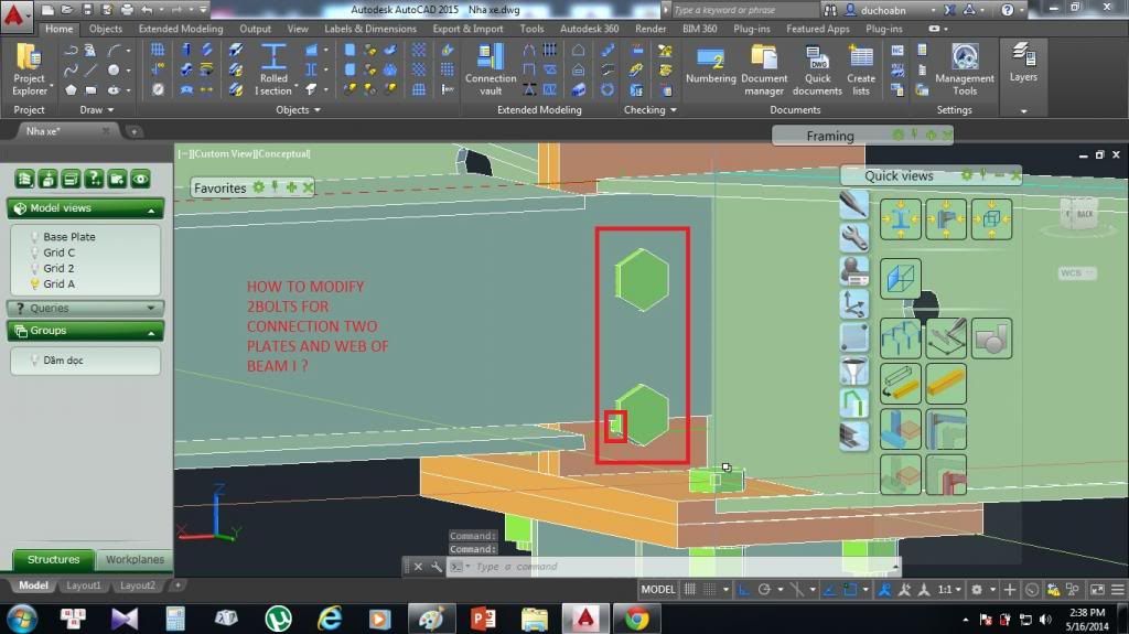
Dear All
In this connection, I was added connection for two beams paraped and created two plates + added bolts
But in picture below have a problem for connection bolts and two plates vertical and Web of Beam I
Please guide me to mofidy two Bolts for this connection
Thanks all
Message 6 of 7
05-16-2014
03:48 AM
- Mark as New
- Bookmark
- Subscribe
- Mute
- Subscribe to RSS Feed
- Permalink
- Report
05-16-2014
03:48 AM
If the bolt is not part of an Advance Steel predefined connection, then you can use the command "Connection, add objects" (_AstM4CommCreateConnection INCL) , found on the "Objects" ribbon / Connection objects panel to add new objects to an existing bolt grip. By doing this, the bolt grip will extend, the washer/nut/bolt head will change position, avoid the collision. Also the new object will be part of the shop/site connection that the bolt realises.
But, if the bolt is part of a connection, you can't add new objects to its grip without exploding the joint. To be part of the grip, the object needs to be part of the input elements onto which the connection is created, or it should be created by the joint.
Dumitru Berteanu
Product Owner
Message 7 of 7
05-21-2014
09:17 AM
- Mark as New
- Bookmark
- Subscribe
- Mute
- Subscribe to RSS Feed
- Permalink
- Report
05-21-2014
09:17 AM
Hi,
with reference to the connection shown, you may consider using the custom connections palette, there are a series of Bricks ( mini macros) that can be used to build a connection from basics, or you can combine these with existing main macros to add to their options. you then create a custom template file which is store in the system and can inserted like a macro joint.
If used correctly this can be a very powerfull tool, as once it is a custom connection you can copy it round the model like other joints, but using commands like Create by Template (joint copy).or the advance copy also works well.
John Bennett
Did you find this post helpful? Feel free to Like this post.
Did your question get successfully answered? Then click on the ACCEPT SOLUTION button.
Reply
Topic Options
- Subscribe to RSS Feed
- Mark Topic as New
- Mark Topic as Read
- Float this Topic for Current User
- Bookmark
- Subscribe
- Printer Friendly Page
