Community
Moldflow Insight Forum
Welcome to Autodesk’s Moldflow Insight Forums. Share your knowledge, ask questions, and explore popular Moldflow Insight topics.
Turn on suggestions
Auto-suggest helps you quickly narrow down your search results by suggesting possible matches as you type.
Reply
Topic Options
- Subscribe to RSS Feed
- Mark Topic as New
- Mark Topic as Read
- Float this Topic for Current User
- Bookmark
- Subscribe
- Printer Friendly Page
Message 1 of 11
03-21-2012
06:27 AM
- Mark as New
- Bookmark
- Subscribe
- Mute
- Subscribe to RSS Feed
- Permalink
- Report
03-21-2012
06:27 AM
3D mesh x Dual domain mesh
Hello,
I'm working with a specymen and Ive made the simulation with a 3D mesh and a Dual domain mesh. Both the mesh follow the mesh criterias of the Moldflow. The problem is that the cycle time result of the 3D mesh is 45% higher.
Anyone know why is that happenning?
Thanks,
André Eccel Vellwock
10 REPLIES 10
Message 2 of 11
03-21-2012
12:06 PM
- Mark as New
- Bookmark
- Subscribe
- Mute
- Subscribe to RSS Feed
- Permalink
- Report
03-21-2012
12:06 PM
Check the thickness diagnostic in Dual domain and make sure it does not under-estimate the thickness distribution. For example the place where two wall intersect is actually a thick area but dual domain may underestimate the thickness. Whle the 3D mesh will more accurately estimate the true volume.
I'd trust 3D more, in general.
That being said, in reality the may be able to eject the part sooner that the 3D estimates if the wall is adequately rigid.
Message 3 of 11
03-22-2012
06:19 AM
- Mark as New
- Bookmark
- Subscribe
- Mute
- Subscribe to RSS Feed
- Permalink
- Report
03-22-2012
06:19 AM
Thanks for your answer.
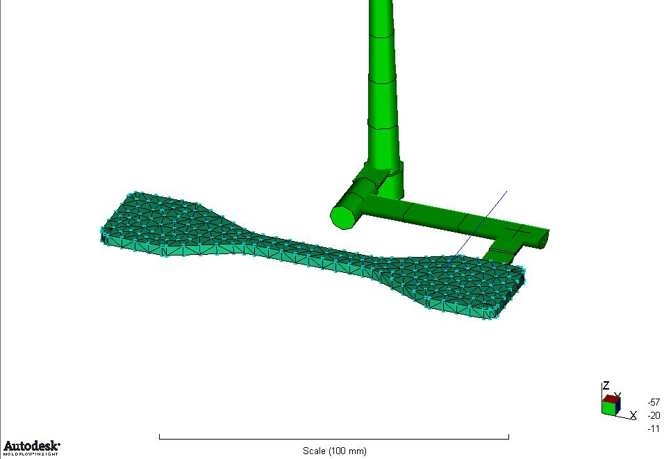
I dont have this problem because the thickness of the wall is constant.
You can see in the printscreen attched that the part is very simple, so the dual domain's volume is the same as the 3D's.
Message 4 of 11
03-22-2012
06:26 AM
- Mark as New
- Bookmark
- Subscribe
- Mute
- Subscribe to RSS Feed
- Permalink
- Report
03-22-2012
06:26 AM
I'd still check the thickness diagnostic for Dual-Domain just to be sure that the thickness assignments are not faulty.
Other than that, i can only advise to re-check you process parameters and resin data between the two different setups.
Perhaps you could also see which area is controlling the cooling time in both the setup and narrow down your problem area.
Message 5 of 11
03-22-2012
08:12 AM
- Mark as New
- Bookmark
- Subscribe
- Mute
- Subscribe to RSS Feed
- Permalink
- Report
03-22-2012
08:12 AM
Hi,
looking at the picture of specimen part, the thinner passage is almost quadratic in cross section.
Then, the mesh will be too coarse for 3D tetras.
Have a look of mesh inside.
A finer mesh overall, and maybe and some layers for 3D (default 6, maybe change to 8 or 10).
This should improve the result.
Regards,
Berndt

Berndt Nordh
Message 6 of 11
03-22-2012
09:15 AM
- Mark as New
- Bookmark
- Subscribe
- Mute
- Subscribe to RSS Feed
- Permalink
- Report
03-22-2012
09:15 AM
Thanks for the reply.
I've improved the mesh quality for the 3D but the cycle time havent changed.
And the thickness is OK in the dual domain mesh.
Message 7 of 11
03-22-2012
10:07 AM
- Mark as New
- Bookmark
- Subscribe
- Mute
- Subscribe to RSS Feed
- Permalink
- Report
03-22-2012
10:07 AM
Hi,
I am not a Moldflow user nor an injection molding engineer, so someone please correct me if I am wrong. I think the part is not suitable for the dual domain analysis. The documentation says that one requirement for dual domain is "the minimum length and width of any local region should be greater than four times the local thickness. A more conservative estimate of ten time the thickness ensures more accurate results".
I believe the dual domain analysis does not consider some (or any?) effects along the edge of the model, so the resin flows more easily through the narrow section in the dual domain analysis than it does in reality.
John Holtz, P.E.
Global Product Support
Autodesk, Inc.
If not provided already, be sure to indicate the version of Inventor Nastran you are using!
"The knowledge you seek is at knowledge.autodesk.com" - Confucius 😉
Message 8 of 11
03-22-2012
11:22 AM
- Mark as New
- Bookmark
- Subscribe
- Mute
- Subscribe to RSS Feed
- Permalink
- Report
03-22-2012
11:22 AM
Sorry, in what documentation have you found this?
I checked in the Moldflow 2011 and the recommendation that Ive found is:
Dual domain mesh -" These layers enable an accurate representation of thin, cross-sectioned parts, where there is a rapidly changing characteristic profile, for example, temperature and flow-front velocity."
But Ive found another interesting thing, check the printscreen, that can be the answer for this.
Actually, the software is prediciting a heat loss in the z direction (the thickness direction). It can be estimating uncorrectly. If this has a relation with the thickness, I cant afirm, because i dont know how the software calculate this heat loss in z direction.
Message 9 of 11
03-22-2012
11:40 AM
- Mark as New
- Bookmark
- Subscribe
- Mute
- Subscribe to RSS Feed
- Permalink
- Report
03-22-2012
11:40 AM
Refreshing:
Ive tried to rotate all the model to see if there is a relation with the coordinate system, but nothing happenned.
Message 10 of 11
03-22-2012
11:50 AM
- Mark as New
- Bookmark
- Subscribe
- Mute
- Subscribe to RSS Feed
- Permalink
- Report
03-22-2012
11:50 AM
Hi,
The passage that I found is from the online 2012 Help: "Choosing an analysis technology".
I presume the passage about estimating the heat losses in the "Z" direction are referring to a local coordinate system where X and Y are in the plane of the element and Z is perpendicular. I would be very surprised if it was referring to the global X, Y, Z directions. So rotating the model should not change the results.
John Holtz, P.E.
Global Product Support
Autodesk, Inc.
If not provided already, be sure to indicate the version of Inventor Nastran you are using!
"The knowledge you seek is at knowledge.autodesk.com" - Confucius 😉
Message 11 of 11
03-22-2012
08:04 PM
- Mark as New
- Bookmark
- Subscribe
- Mute
- Subscribe to RSS Feed
- Permalink
- Report
03-22-2012
08:04 PM
I would be very surprised too. But Im trying everything now.
So I also changed the local coordinate system, but the cycle time is still the same.
I think I will agree with you and accept that the simulation with the 3D msh is better and more reliable.
Thanks again,
André Eccel Vellwock
Undergraduate student, Mechanical Engineering, UFSC
Researcher, CIMJECT
Reply
Topic Options
- Subscribe to RSS Feed
- Mark Topic as New
- Mark Topic as Read
- Float this Topic for Current User
- Bookmark
- Subscribe
- Printer Friendly Page
