Community
- Forums Home
- >
- Moldflow Adviser Community
- >
- Moldflow Adviser Forum
- >
- Opposite colours in warpage result?
Moldflow Adviser Forum
Welcome to Autodesk’s Moldflow Adviser Forums. Share your knowledge, ask questions, and explore popular Moldflow Adviser topics.
Turn on suggestions
Auto-suggest helps you quickly narrow down your search results by suggesting possible matches as you type.
Reply
Topic Options
- Subscribe to RSS Feed
- Mark Topic as New
- Mark Topic as Read
- Float this Topic for Current User
- Bookmark
- Subscribe
- Printer Friendly Page
Message 1 of 2
Anonymous
630 Views, 1 Reply
03-21-2013
07:58 AM
- Mark as New
- Bookmark
- Subscribe
- Mute
- Subscribe to RSS Feed
- Permalink
- Report
03-21-2013
07:58 AM
Opposite colours in warpage result?
Hello Autodesk friends,
I am user of Moldflow Adviser 2012 and I would like to ask you for help with following problem:
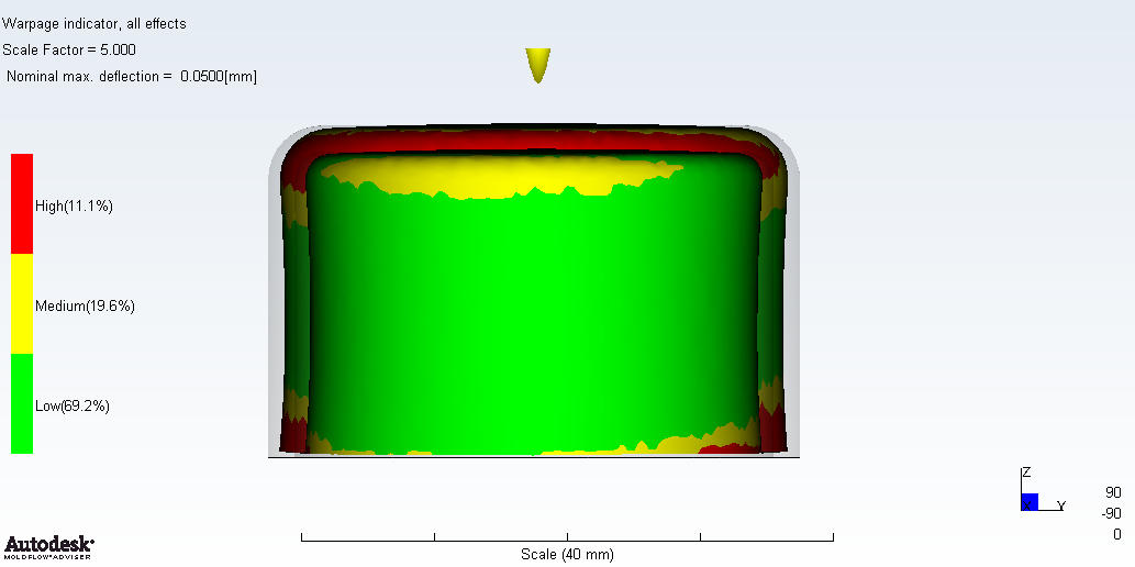
Result from warpage analysis (dual domain) shows hight deflection colored by red and low deflection by green colour. But in figure down captured from my result there is a heighest gaps betwen original and deformed shape in the area of green, and lowest gaps in the area of red colour.
Please hepl me, how can I understand this result.... Thak you very much!

1 REPLY 1
Message 2 of 2
04-16-2013
03:31 AM
- Mark as New
- Bookmark
- Subscribe
- Mute
- Subscribe to RSS Feed
- Permalink
- Report
04-16-2013
03:31 AM
Hi,
the reason for this is which reference the deflection result is using when displayed.
By default it uses a best fit.
You can set a Anchor Plane as a reference, or pick your own reference points for a best fit.
The deflection magnitude is the same, but you change the reference how to display the deflection.
When result is displayed, you can do this setup on how to display results in tab Tools.
See Help for information, or wikihelp at:
http://wikihelp.autodesk.com/Simulation_Moldflow/enu/2013/Help/4Adviser/1747-Results1747/1880-Warp_a...
Having a cylindrical part, as I see it, you need to set/change the reference to evaluate/analyze the result.
Also, the warp result is shrinkage and deflection.
The max deflection is quite low too: Nominal Max Deflection set to 0.05mm
Meaning:
Green : < 80% of 0.05 mm: < 0.04 mm
Yellow : 80-120% of 0.05 mm : 0.04-0.06 mm
Red : > 120% of 0.05 mm : > 0,06 mm
Hope this helps.
Regards,


Berndt
Berndt Nordh
Reply
Topic Options
- Subscribe to RSS Feed
- Mark Topic as New
- Mark Topic as Read
- Float this Topic for Current User
- Bookmark
- Subscribe
- Printer Friendly Page
