Community
- Forums Home
- >
- Community Archive - Read Only
- >
- Simulation Mechanical Community
- >
- Simulation Mechanical Forum
- >
- Re: plate element thickness
Simulation Mechanical Forums (Read-Only)
Welcome to Autodesk’s Simulation Mechanical Forums. Share your knowledge, ask questions, and explore popular Simulation Mechanical topics.
Turn on suggestions
Auto-suggest helps you quickly narrow down your search results by suggesting possible matches as you type.
Reply
Topic Options
- Subscribe to RSS Feed
- Mark Topic as New
- Mark Topic as Read
- Float this Topic for Current User
- Bookmark
- Subscribe
- Printer Friendly Page
Message 1 of 8
Anonymous
1859 Views, 7 Replies
02-25-2013
11:16 AM
- Mark as New
- Bookmark
- Subscribe
- Mute
- Subscribe to RSS Feed
- Permalink
- Report
02-25-2013
11:16 AM
if a meshed plate with plate elemnts got say 3 elements across the thickness.....then what would be the element thickness. if iam meshing 1 inch thick plate.....what would be element thickenss....1/3??
Solved! Go to Solution.
Solved by AstroJohnPE. Go to Solution.
7 REPLIES 7
Message 2 of 8
02-25-2013
12:27 PM
- Mark as New
- Bookmark
- Subscribe
- Mute
- Subscribe to RSS Feed
- Permalink
- Report
02-25-2013
12:27 PM
Hi madg1,
Something does not sound right in your question. Perhaps you are confusing the suggestion of "multiple layers of brick elements through the thickness" with multiple plate elements.
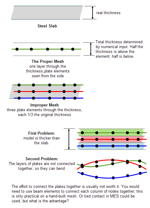
Because it can get confusing when talking about plate elements to represent a steel "plate", let me use the words "steel slab" instead of the steel plate.
The plate element mesh must represent the entire thickness of the slab. You do not need to use multiple plate elements through the thickness of the slab. Perhaps the descriptions on the pages "Model Mesh Settings" (3 figures on the page) and "Plate Elements" (Figure 1) will help to explain the concept -- assuming that you are starting from a CAD model.
If you were to mesh the slab with 3 plate elements through the thickness, you would be representing 3 slabs sitting on top of each other. But the 3 layers of plate elements would not be connected together, so they would be able to move independent of each other. I have attached some crude images to try to clarify my explanation.
Reply
Message 3 of 8
02-25-2013
01:56 PM
- Mark as New
- Bookmark
- Subscribe
- Mute
- Subscribe to RSS Feed
- Permalink
- Report
02-25-2013
01:56 PM
what happens if i put a refinement point at one node.....it will become multiple element thick right>?
Message 4 of 8
02-26-2013
12:11 PM
- Mark as New
- Bookmark
- Subscribe
- Mute
- Subscribe to RSS Feed
- Permalink
- Report
Message 6 of 8
02-27-2013
02:49 PM
- Mark as New
- Bookmark
- Subscribe
- Mute
- Subscribe to RSS Feed
- Permalink
- Report
02-27-2013
02:49 PM
Hi,
What I see is a large plate/slab of material that was bent to form an "L" shape: the red item (surface?) is the long leg of the "L", and the blue item (surface?) is the short leg of the "L". The blue item does not represent the thickness of the red part; not when both are defined with an element type of "Plate".
Just do a Check Model ("Analysis > Analysis > Check Model") and slice the model ("Results Options > Slice Planes > Add Slice Plane > pick one that gives a view similar to the attached sketch).
Another way to see what you are modeling when working with plate elements is to select the part(s) in the Results environment, right-click, and choose "3D Visualization". This will show the thickness of the plates. What you see is what you have modeled. If it matches the physical structure, then you are okay.
Message 8 of 8
03-05-2013
03:43 PM
- Mark as New
- Bookmark
- Subscribe
- Mute
- Subscribe to RSS Feed
- Permalink
- Report
03-05-2013
03:43 PM
Hello Everyone,
Just in case there is any confusion, whether now or in the future, I created the attached paper to describe the different mesh types (solid, midplane, plate/shell) and when to use each one. Any feedback would be welcomed, either privately or in this thread.
In another thread, Sualp posted this link to a great video that also describes the different mesh types. If you are using midplane or plate/shell mesh type for the first time, I highly recommend you watch the video. (If I had watched it before creating the attached paper, I probably would not have created it. ![]() )
)
Reply
Topic Options
- Subscribe to RSS Feed
- Mark Topic as New
- Mark Topic as Read
- Float this Topic for Current User
- Bookmark
- Subscribe
- Printer Friendly Page
Forums Links
Can't find what you're looking for? Ask the community or share your knowledge.
Post to forums
