Community
- Forums Home
- >
- Community Archive - Read Only
- >
- Simulation Mechanical Community
- >
- Simulation Mechanical Forum
- >
- Re: Unable to mesh a 2d model imported from Rhino 5
Simulation Mechanical Forums (Read-Only)
Welcome to Autodesk’s Simulation Mechanical Forums. Share your knowledge, ask questions, and explore popular Simulation Mechanical topics.
Turn on suggestions
Auto-suggest helps you quickly narrow down your search results by suggesting possible matches as you type.
Unable to mesh a 2d model imported from Rhino 5
16 REPLIES 16
SOLVED
Reply
Topic Options
- Subscribe to RSS Feed
- Mark Topic as New
- Mark Topic as Read
- Float this Topic for Current User
- Bookmark
- Subscribe
- Printer Friendly Page
Message 1 of 17
06-30-2014
01:45 AM
- Mark as New
- Bookmark
- Subscribe
- Mute
- Subscribe to RSS Feed
- Permalink
- Report
06-30-2014
01:45 AM
Dear All,
Hi, I am currently working on an insect wing simulation project, whereby i have enclosed my models for your kind perusal. I have been trying to mesh the models in 2d with little success. It keeps on saying the wireframe does not enclose a single area. I would like to simulate my wing in a flapping motion and I have no idea what went wrong. I created my model in Rhino 5 and imported it as a .dwg model because .iges and .stp failed. Could you please suggest an alternate option to help me with my project? Please help. I have changed the plane into YZ and nothing seems to work. If I have to re-create my drawing do let me know as well. Thanks
Solved! Go to Solution.
Solved by AstroJohnPE. Go to Solution.
Solved by AstroJohnPE. Go to Solution.
16 REPLIES 16
Message 2 of 17
06-30-2014
08:40 AM
- Mark as New
- Bookmark
- Subscribe
- Mute
- Subscribe to RSS Feed
- Permalink
- Report
06-30-2014
08:40 AM
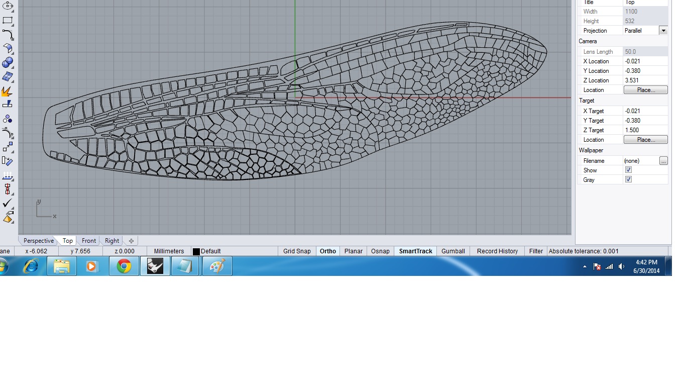
According to the Help documentation, each region that you want to mesh needs to be on a different part number. In the cidada drawing, I count up 18 different regions. Therefore, the wing needs to be drawn on 18 different parts. (If you isolate part 1, it will be a complete outline of section 1. Isolate part 2, and it will be a complete outline of a different section. And so on.) Your image shows that everything is in part 1.
It is probably the same issue for the dragonfly wing, but there are too many regions for me to count. ![]()
But before you go to the trouble of creating 18 complete parts, I am curious to know
- what are the details of your analysis? (analysis type, element type, loads, constraints, etc)
- is it really necessary to have the mesh follow the pattern you have drawn? If so, why?

Reply
Message 3 of 17
07-02-2014
01:51 AM
- Mark as New
- Bookmark
- Subscribe
- Mute
- Subscribe to RSS Feed
- Permalink
- Report
07-02-2014
01:51 AM
Mr. John,
I am finally able to mesh my cicada model and currently working with the analysis report. The trouble is still with my dragonfly wing, I am planning to work on a static analysis. Element would be 2D and the BC would be at the root of the wing, a concentrated force on the edge of the wing. Perhaps I do not need to mesh the whole model as you had suggested...only the tip and the root would do. Yet when I have imported my model from Rhino to Autodesk, my polylines are recognized as different vertices...and I have no idea on how to combine them into one...also if i create a 2d mesh, it is not able to mesh the whole part maybe due to the complexity. How do I separate parts? Will it not be possible for me to choose to mesh only the root and the edge of the wing and look at the changes?
Hoping very much for your reply, my due date is nearing and I am in a panic state at the moment.
Thanks and God Bless
Message 4 of 17
07-02-2014
09:19 AM
- Mark as New
- Bookmark
- Subscribe
- Mute
- Subscribe to RSS Feed
- Permalink
- Report
07-02-2014
09:19 AM
Sorry if my question 2 was not clear. I was not suggesting to mesh a limited portion of the wing ("only the tip and the root would do"). I am suggesting that you mesh the entire wing. But instead of using 18 parts for the cicada wing so that the final meshed model looks like this (where each color and number represents a different part):

I am suggesting that you make the entire wing one part so that it looks like this:

Delete all of the interior lines from the wireframe and just leave the outline. This will give you a mesh of the entire wing. Of course, the random mesh does not follow the 18 regions, so my question was intended to be "does the mesh need to follow the 18 regions"?
To fix the problems with the imported wireframe, you can use the commands on the "Draw" menu -- assuming that you cannot fix them in the original drawing or by changing the "Tolerance" on the "2-D Mesh Generation" dialog. You may need to draw lines in Simulation Mechanical to connect the endpoints that are not connected together, or trim off a portion of the existing wireframe and replace it with a longer line or arc or spline.
If you want some practice with drawing, you can use either of these documents:
- the tutorial titled "2-D Weldment Model" located in the "Start & Learn > Learn > Tutorials"
- the page titled "Water-Cooled Wall with Radiation, Convection, and Temperature Model" located in the "Start & Learn > Learn > Help > User's Guide > Examples > Modeling" section of the help documentation.
Reply
Message 5 of 17
07-06-2014
10:47 PM
- Mark as New
- Bookmark
- Subscribe
- Mute
- Subscribe to RSS Feed
- Permalink
- Report
07-06-2014
10:47 PM
Hello John,
Thank you for your response and I am glad to have someone to assist me. I am finally able to mesh both my models using a 2d mesh...I have created the hindwing of the dragonfly as well and now it is facing the same problem. The error message is just that the mesh could not be generated succesfully. Previously, after doing many modifications, the mesh was created after refining the mesh size. For the model that I have created now, what do you think would be the suitable geometric ratio, layer factor, angle, density and so on. I would like to use mixed elements for my meshing purpose. I have attached my wing model for your perusal. Please do have a look.
Message 6 of 17
07-07-2014
05:58 AM
- Mark as New
- Bookmark
- Subscribe
- Mute
- Subscribe to RSS Feed
- Permalink
- Report
07-07-2014
05:58 AM
Why are you using so many regions in the model? How do the regions affect the engineering or analysis?
Message 7 of 17
07-07-2014
12:53 PM
- Mark as New
- Bookmark
- Subscribe
- Mute
- Subscribe to RSS Feed
- Permalink
- Report
07-07-2014
12:53 PM
Hello
The question is are you going to assign different thickness to each area?
If i understand correctly the image of the dragon you are going to have two different thickness, the thickness of the wind skeleton or frame and the thickness of the area between the frame. am I correct?
I transfer the model to my autocad 2015 and i didnt get the areas, only lines, I created the areas for each zone , I make a substract boolean operation and get 901 parts I checked in my Autodesk simulation and the model is working. I leave you the autocad file each area as an element.
Wilmer Ariza
Researcher Control and SI with AI for autonomous underwater vehicles
PhD student(Australian Maritime College-University of Tasmania)
Master of engineering (Advance Manufacturing Technology- Swinburne University of Technology)
Mechatronic Engineer
Researcher Control and SI with AI for autonomous underwater vehicles
PhD student(Australian Maritime College-University of Tasmania)
Master of engineering (Advance Manufacturing Technology- Swinburne University of Technology)
Mechatronic Engineer
Message 8 of 17
07-08-2014
06:16 AM
- Mark as New
- Bookmark
- Subscribe
- Mute
- Subscribe to RSS Feed
- Permalink
- Report
07-08-2014
06:16 AM
This is the result of the mesh

Wilmer Ariza
Researcher Control and SI with AI for autonomous underwater vehicles
PhD student(Australian Maritime College-University of Tasmania)
Master of engineering (Advance Manufacturing Technology- Swinburne University of Technology)
Mechatronic Engineer
Researcher Control and SI with AI for autonomous underwater vehicles
PhD student(Australian Maritime College-University of Tasmania)
Master of engineering (Advance Manufacturing Technology- Swinburne University of Technology)
Mechatronic Engineer
Reply
Message 9 of 17
07-08-2014
08:19 AM
- Mark as New
- Bookmark
- Subscribe
- Mute
- Subscribe to RSS Feed
- Permalink
- Report
07-08-2014
08:19 AM
Thank you very very much....I shall try this in autocad 2015...i have never used autocad 2015 before...only rhino...i have no idea on how to do it in autocad 2015.... looking at your mesh i guess my earlier wings was not meshed properly...i am truly grateful for your help...shall try this and find out how can this be done....by the way...what element did u used to mesh the model...is it 2d?
Thank you very much and you have saved my day....god bless u..thanks again...do keep in touch please as i need to try it out and get back to u if i face any complications....
Message 10 of 17
07-08-2014
11:39 AM
- Mark as New
- Bookmark
- Subscribe
- Mute
- Subscribe to RSS Feed
- Permalink
- Report
07-08-2014
11:39 AM
Yes I used a shell element/plate element.
Wilmer Ariza
Researcher Control and SI with AI for autonomous underwater vehicles
PhD student(Australian Maritime College-University of Tasmania)
Master of engineering (Advance Manufacturing Technology- Swinburne University of Technology)
Mechatronic Engineer
Researcher Control and SI with AI for autonomous underwater vehicles
PhD student(Australian Maritime College-University of Tasmania)
Master of engineering (Advance Manufacturing Technology- Swinburne University of Technology)
Mechatronic Engineer
Message 11 of 17
07-08-2014
11:34 PM
- Mark as New
- Bookmark
- Subscribe
- Mute
- Subscribe to RSS Feed
- Permalink
- Report
07-08-2014
11:34 PM
Hello,
I am viewing at your model in autodesk simulation. Did you assign the elements individually for all 901 parts? Is there any way to assign the same elements for all? And after that did you just click generate 3d mesh?
Message 12 of 17
07-08-2014
11:45 PM
- Mark as New
- Bookmark
- Subscribe
- Mute
- Subscribe to RSS Feed
- Permalink
- Report
07-08-2014
11:45 PM
Hello,
Here is what I did:
I opened the.dwg file that you've attached in AutoDesk Simulation, I assigned plate element for all. And I clicked generate 3d mesh. It say surfacemesh scoring error. Please help.
What must I do?
Thanks
Message 13 of 17
07-09-2014
12:50 AM
- Mark as New
- Bookmark
- Subscribe
- Mute
- Subscribe to RSS Feed
- Permalink
- Report
07-09-2014
12:50 AM
hello again.
i went to mes settings, and now its meshing....problem is its now in part 1 and is taking soooo long to mesh...was urs the same too?....sorry for posting many questions....im just kinda helpless....sorry and thanks
Message 14 of 17
07-09-2014
06:13 AM
- Mark as New
- Bookmark
- Subscribe
- Mute
- Subscribe to RSS Feed
- Permalink
- Report
07-09-2014
06:13 AM
yes .usually part 1 takes long time but after that he is faster. the delay is the creation of the data needed to mesh all the elelements. You have to consider that part A mesh is going to share elements with Part B. In my workstation takes 30 minutes to mesh that is not unusual to this type of models
Wilmer Ariza
Researcher Control and SI with AI for autonomous underwater vehicles
PhD student(Australian Maritime College-University of Tasmania)
Master of engineering (Advance Manufacturing Technology- Swinburne University of Technology)
Mechatronic Engineer
Researcher Control and SI with AI for autonomous underwater vehicles
PhD student(Australian Maritime College-University of Tasmania)
Master of engineering (Advance Manufacturing Technology- Swinburne University of Technology)
Mechatronic Engineer
Reply
Message 15 of 17
07-09-2014
07:43 PM
- Mark as New
- Bookmark
- Subscribe
- Mute
- Subscribe to RSS Feed
- Permalink
- Report
07-09-2014
07:43 PM
Dear txfingenieria,
I have finally meshed the model. I just need one final help from you, please? How did you create the areas in AutoCAD 2015? Which command must you select and what must you do in order to obtain the model you made for me? Please help as I am new to AUTOCAD 2015. Please and thanks.....God bless
Message 16 of 17
07-10-2014
06:15 AM
- Mark as New
- Bookmark
- Subscribe
- Mute
- Subscribe to RSS Feed
- Permalink
- Report
07-10-2014
06:15 AM
Sure i write a small tutorial of what i did
first i detect the error when i watch the size of the dwg file.
Too small to have al that areas describe.
This is how your file looks in autodesk.

To create the areas we use the command REGION. You dont have to go one by one. select all the areas and enter.

You are going to get all areas a big external area and small internal areas


Now is the enteristing part. you have to copy the internal areas. You select everything and unselect the external area and then CTRL+C.


To substract the small areas from the big one we use the commands SUBSTRACT

Select again external area+enter then internal areas without external area and enter.

Know you can do a CTRL+V 0,0 to set the paste in the origen and your going to get all the small areas back.
Wilmer Ariza
Researcher Control and SI with AI for autonomous underwater vehicles
PhD student(Australian Maritime College-University of Tasmania)
Master of engineering (Advance Manufacturing Technology- Swinburne University of Technology)
Mechatronic Engineer
Researcher Control and SI with AI for autonomous underwater vehicles
PhD student(Australian Maritime College-University of Tasmania)
Master of engineering (Advance Manufacturing Technology- Swinburne University of Technology)
Mechatronic Engineer
Reply
Message 17 of 17
07-22-2014
01:53 AM
- Mark as New
- Bookmark
- Subscribe
- Mute
- Subscribe to RSS Feed
- Permalink
- Report
07-22-2014
01:53 AM
Hi,
Thank you so very much for your step by step tutorial. I am very sory for the late reply, as I was away for a project with my project members. Just got back yesterday. I tried your tutorial but unfortunately it still failed. I have no idea where the mistake is and I keep on doing it again and again...this is for the forewing of the dragonfly.... When I control V at the end...there seem to be two separate drawings...one with only th internal areas and one with both internal and external areas..... also, when u meant selecting external areas, is it only the outline framework? or is there anything else that i should select?
Sorry for troubling you again and again...sincerely appreciate your help...god bless
Reply
Topic Options
- Subscribe to RSS Feed
- Mark Topic as New
- Mark Topic as Read
- Float this Topic for Current User
- Bookmark
- Subscribe
- Printer Friendly Page
