Community
CFD Forum
Welcome to Autodesk’s CFD Forums. Share your knowledge, ask questions, and explore popular CFD topics.
Turn on suggestions
Auto-suggest helps you quickly narrow down your search results by suggesting possible matches as you type.
Reply
Topic Options
- Subscribe to RSS Feed
- Mark Topic as New
- Mark Topic as Read
- Float this Topic for Current User
- Bookmark
- Subscribe
- Printer Friendly Page
Message 1 of 17
Anonymous
1545 Views, 16 Replies
10-25-2011
02:56 PM
- Mark as New
- Bookmark
- Subscribe
- Mute
- Subscribe to RSS Feed
- Permalink
- Report
10-25-2011
02:56 PM
Torque output in 2D rotational analysis
I have an issue with the torque output from a 2D rotating surface for a while now and really need to have this figured out as quickly as possible. I wonder if anyone else has the same issue or could shed some light on this.
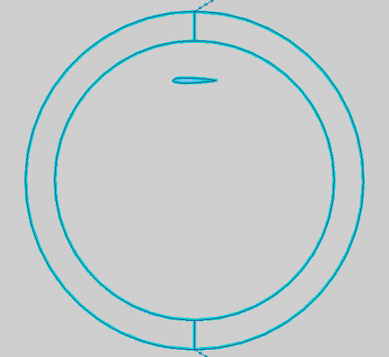
I take a single symmetric airfoil like a NACA0012 and put it in a rotating surface that is circular with the center sitting at the origin (see diagram). I do have a larger air domain around it. I set the material, RPM, mesh and put in a 3-degree-timestamp. The boundary condition is set to no wind speed since I am isolating the torque results. I run it for 4,800 iterations and the torque.csv is created at the end of the run.
Over the last full revolution with 30-degree interval, I try to match the hydraulic torque to the hydraulic forces (X and Y) in the csv file, but I find the calculated torque does not agree with the raw hydraulic torque output (see chart). I have accounted for the moment of the airfoil and added that to the calculated torque. The moment of the airfoil is obtained from the wall calculation at each 30-degree interval over a full revolution at the 25% point of the airfoil's chord.
I throw the wall calculation torque in the chart just for the sake of curiosity. I am well-aware that getting rotating torque results from the wall calculation is not recommended.
This torque issue is observed in both Simulation CFD 2012 and CFdesign 2010.
16 REPLIES 16
Message 2 of 17
10-26-2011
03:35 AM
- Mark as New
- Bookmark
- Subscribe
- Mute
- Subscribe to RSS Feed
- Permalink
- Report
10-26-2011
03:35 AM
Hi,
what do you mean with no wind speed? A specified velocity condition of 0? Can you give us an complete overview of the boundary conditions or even attach a share file to your post?
Does the same difference of the "force-torque" and torque appear for different mesh sizes?
Marco Müller
Product Support Specialist
Digital Simulation
Autodesk, Inc.
Message 3 of 17
10-26-2011
07:34 AM
- Mark as New
- Bookmark
- Subscribe
- Mute
- Subscribe to RSS Feed
- Permalink
- Report
10-26-2011
07:34 AM
Marco, attached is the share file with the single airfoil. The scenario has a close-to-zero wind speed of 1e-06 mph in the positive X direction.
I was wondering if the hydraulic torque from the csv file is directly related to the hydraulic forces X and Y (or vice versa)? Or are these outputs solved implicitly from different sources?
I have not tried different mesh sizes yet, but I will definitely try that now. Thanks for the idea, Marco. I will post my findings once that is done.
Message 4 of 17
10-27-2011
01:07 AM
- Mark as New
- Bookmark
- Subscribe
- Mute
- Subscribe to RSS Feed
- Permalink
- Report
10-27-2011
01:07 AM
Of course, they should be comparable. But to check this I'd eliminate some error sources. I've found that the rotation region is not perfectly rotating around its center, that's why there occur cyclical issues during the solution:

Also the mesh near the interface line can be finer since there is a (small) shift of the values around it:

A side note: I'd uncheck the output of all quantities that are not relevant for you. Especially the calculation of LMA needs additional ressources (and is anyway not necessary during the solution), so if you uncheck this you will see a tremendous speed-up of the simulation.
Marco Müller
Product Support Specialist
Digital Simulation
Autodesk, Inc.
Message 5 of 17
10-27-2011
02:08 PM
- Mark as New
- Bookmark
- Subscribe
- Mute
- Subscribe to RSS Feed
- Permalink
- Report
10-27-2011
02:08 PM
Yes, I also observed that strange gap between the rotating and static region. There was no intentional gap created and the rotating region center is placed at 0,0,0 in the CAD file. In the CAD file, the rotating region is just a surface that sit on top of the overall air domain surface.
Could there be something wrong that is throwing the rotaional center off?
I tried to make another CAD file where the rotating region was "cookie-cut" out from the rest of the region (separated between the regions), but again I saw the gap appearing when the simulation started to run.
Any suggestions to remove this unwanted gap and keep the rotating region at 0,0,0?
Message 6 of 17
10-27-2011
02:36 PM
- Mark as New
- Bookmark
- Subscribe
- Mute
- Subscribe to RSS Feed
- Permalink
- Report
10-27-2011
02:36 PM
Hi Max,
Could you attach your native CAD files? I am not sure why we are not getting a perfect rotation based on what I am looking at.
Thanks,
Royce
Royce.Abel
Technical Support Manager
Message 7 of 17
10-27-2011
03:00 PM
- Mark as New
- Bookmark
- Subscribe
- Mute
- Subscribe to RSS Feed
- Permalink
- Report
Message 8 of 17
10-27-2011
03:02 PM
- Mark as New
- Bookmark
- Subscribe
- Mute
- Subscribe to RSS Feed
- Permalink
- Report
10-27-2011
03:02 PM
What CAD package did you use to generate it?
-Royce
Royce.Abel
Technical Support Manager
Message 9 of 17
10-27-2011
03:27 PM
- Mark as New
- Bookmark
- Subscribe
- Mute
- Subscribe to RSS Feed
- Permalink
- Report
10-27-2011
03:27 PM
I use a CAD software named Shark FX. Do you prefer a parasolid file to work with?
Message 10 of 17
10-31-2011
03:17 AM
- Mark as New
- Bookmark
- Subscribe
- Mute
- Subscribe to RSS Feed
- Permalink
- Report
10-31-2011
03:17 AM
Can you try to export parasolid or ACIS and then load them into Inventor Fusion which is part of the Simulation package and then start the simulation from Fusion?
Marco Müller
Product Support Specialist
Digital Simulation
Autodesk, Inc.
Message 11 of 17
10-31-2011
09:11 AM
- Mark as New
- Bookmark
- Subscribe
- Mute
- Subscribe to RSS Feed
- Permalink
- Report
10-31-2011
09:11 AM
I will try using Inventor Fusion to load the exported parasolid. Could this offset in rotation due to the inertia offset since there is only one airfoil in the rotation region?
Message 12 of 17
11-01-2011
12:56 AM
- Mark as New
- Bookmark
- Subscribe
- Mute
- Subscribe to RSS Feed
- Permalink
- Report
11-01-2011
12:56 AM
This should not be the reason. The motion is independent of the geometry. One thing you can also try to get a more accurate solution is to move the rotating region further away from the airfoil.
Marco Müller
Product Support Specialist
Digital Simulation
Autodesk, Inc.
Message 13 of 17
11-01-2011
09:49 AM
- Mark as New
- Bookmark
- Subscribe
- Mute
- Subscribe to RSS Feed
- Permalink
- Report
11-01-2011
09:49 AM
Marco, I increased the rotating region radius by 20 percent, but I am still seeing the gap once the rotation starts.
Please see attached pictures. The first picture shows the enlarged rotating region and the second picture shows the closeup view of the gap at the top (12 o' clock) location of the rotating region.
Message 14 of 17
11-02-2011
02:23 AM
- Mark as New
- Bookmark
- Subscribe
- Mute
- Subscribe to RSS Feed
- Permalink
- Report
11-02-2011
02:23 AM
Hi Max,
increasing the RR was just suggested to get a better mesh around the airfoil and keep the RR a bit away from areas of high gradients, not for the offset issue.
The gap seems to be around 0.1 ft only in y direction. Maybe you can try to move the RR in your CAD system by 0.04905 ft (got this value from the results) in negative y direction. This is for sure not elegant but may be a workaround if we stay in the tolerances for the RR calculation.
Marco Müller
Product Support Specialist
Digital Simulation
Autodesk, Inc.
Message 15 of 17
11-03-2011
07:18 AM
- Mark as New
- Bookmark
- Subscribe
- Mute
- Subscribe to RSS Feed
- Permalink
- Report
11-03-2011
07:18 AM
Did you have any luck trying to import either the parasolid, acis, or step format into Fusion?
I think Marco and I might agree that the issue with the 'gap' has to do with the accuracy of the geometry from your CAD package.
Might want to also try making the geometry in Fusion from scratch if importing translated geometry doesn't help.
-Royce
Royce.Abel
Technical Support Manager
Message 16 of 17
11-03-2011
03:16 PM
- Mark as New
- Bookmark
- Subscribe
- Mute
- Subscribe to RSS Feed
- Permalink
- Report
11-03-2011
03:16 PM
Importing the acis format to Fusion has not been successful. I probably need to figure out how to work Fusion first. I will also try to make the geometry in Fusion if the import method fails.
I will keep you guys posted.
Message 17 of 17
11-08-2011
06:25 AM
- Mark as New
- Bookmark
- Subscribe
- Mute
- Subscribe to RSS Feed
- Permalink
- Report
11-08-2011
06:25 AM
Max
Do you have more questions on this vs what we discussed with your previous case?
Let me know
Apolo
Reply
Topic Options
- Subscribe to RSS Feed
- Mark Topic as New
- Mark Topic as Read
- Float this Topic for Current User
- Bookmark
- Subscribe
- Printer Friendly Page
Forums Links
Can't find what you're looking for? Ask the community or share your knowledge.
Post to forums
