Community
CFD Forum
Welcome to Autodesk’s CFD Forums. Share your knowledge, ask questions, and explore popular CFD topics.
Turn on suggestions
Auto-suggest helps you quickly narrow down your search results by suggesting possible matches as you type.
Reply
Topic Options
- Subscribe to RSS Feed
- Mark Topic as New
- Mark Topic as Read
- Float this Topic for Current User
- Bookmark
- Subscribe
- Printer Friendly Page
Message 1 of 12
10-09-2012
08:45 AM
- Mark as New
- Bookmark
- Subscribe
- Mute
- Subscribe to RSS Feed
- Permalink
- Report
10-09-2012
08:45 AM
Some clarifications
Hello,
I have started using Autodesk Simulation CFD at work and I have some questions:
1) I am modelling conical perforated filter as resistance and using a shell approach. Meaning, I will model the internals of filter as a fluid domain and the surface as resistance with a finite thickness. Admittedly, this approach is easier. But I am afraid if am losing some physics here. All the flow emanating from the resistance is perpendicular to conical surface, regardless of the direction of its entry; a fact that can be attributed to the inherent modelling of "surface resistances" in Simulation CFD. When I try to model the filter as a cylindrical part with thickness, SimCFD throws an error that says material devices (resistance) should have at least two surfaces in contact with fluid. I know there are two surfaces in fluid contact. Yet why do I get this error?
2) Does SimCFD have any bounded scheme for discretisation, which will smear out the wiggles at the discontinuities or large gradient areas?
3) The jump of mesh size is way too high when mesh switches from prism layers adjacent to wall to inner cells. Would this jump cause loss of physics?
4) Does SimCFD support the meshes created in other dedicated meshes, like say ICEM CFD or TGrid?
Sorry for the long post, but I switched from ANSYS solvers and there are many things I am curious about.
Cheers
OJ
11 REPLIES 11
Message 3 of 12
10-15-2012
02:12 AM
- Mark as New
- Bookmark
- Subscribe
- Mute
- Subscribe to RSS Feed
- Permalink
- Report
10-15-2012
02:12 AM
Hi, I can help with some of this:
1) Try using the other directions available within the material setup, the 2 normal directions. This ought to allow you greater scope regarding the flow direction
2) Do you mean something like the mesh adaption or meshing regions or purely a graphical solution?
3) No, you should be fine, would help to see an example though. If you wish to refine the mesh though, you of course can do. There are many mesh controls available within the advanced and enhancement settings.
4) No, best to use our mesher. It does work very well, although the approach can seem different.
Jon Wilde
Technical Support Manager
CFD Knowledge Network | CFD Help | My Screencasts | Autodesk Simuation YouTube | CFD Tutorials
Message 4 of 12
10-16-2012
05:18 AM
- Mark as New
- Bookmark
- Subscribe
- Mute
- Subscribe to RSS Feed
- Permalink
- Report
10-16-2012
05:18 AM
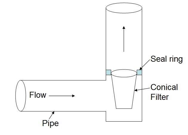
#1 : Please refer to the attached image. The conical filter is perfectly surrounded by fluid domain. I have tried flow direction as both "Radial" and "perpendicular to conical surface". Additionally, I define the axial (to cone) direction as another normal direction. But no success. To reiterate, I am modelling the cylinder as actual cylindrical part with thickness, and not using surface shell resistance.
#2: I was taking about discretization schemes for advection/turbulence. If the second order schemes tend to oscillate near discontinuities and sharp gradients. While first order schemes, though smooth near discontinuities, are inaccurate due to diffusion. I wanted to understand if SimCFD has a bounded second order scheme, preferably monotonous.
Thanks for clarifications.
OJ
Message 5 of 12
10-16-2012
05:41 AM
- Mark as New
- Bookmark
- Subscribe
- Mute
- Subscribe to RSS Feed
- Permalink
- Report
10-16-2012
05:41 AM
How are the directional settings within the material setup though? Could you attach a cfz file?
Jon Wilde
Technical Support Manager
CFD Knowledge Network | CFD Help | My Screencasts | Autodesk Simuation YouTube | CFD Tutorials
Message 8 of 12
10-16-2012
05:58 AM
- Mark as New
- Bookmark
- Subscribe
- Mute
- Subscribe to RSS Feed
- Permalink
- Report
10-16-2012
05:58 AM
I can try!
Have you tried changing the directional settings within the material? There are 3.
Jon Wilde
Technical Support Manager
CFD Knowledge Network | CFD Help | My Screencasts | Autodesk Simuation YouTube | CFD Tutorials
Message 9 of 12
10-17-2012
03:07 AM
- Mark as New
- Bookmark
- Subscribe
- Mute
- Subscribe to RSS Feed
- Permalink
- Report
10-17-2012
03:07 AM
Am not sure if I understand what you mean by directional settings. The only one that seems appropriate is flow direction towards radial and normal direction 1 along axis (going up). Admittedly, I haven't explicitly defined normal dimension 2. Is that what you are hinting? I chose this approach as it is in alignment with the HVAC tutorial.
Can you suggest specifically, how I should try to set the flow direction, normal direction 1 and normal direction 2, in all possible combination that you consider appropriate for this modelling?
Thanks
OJ
Message 10 of 12
10-17-2012
03:40 AM
- Mark as New
- Bookmark
- Subscribe
- Mute
- Subscribe to RSS Feed
- Permalink
- Report
10-17-2012
03:40 AM
If each direction were set to 0.5 (Free Area Ratio) then the flow would be able to travel at any direction through the media. This is what you were asking initially if I am correct? How to allow the flow to travel in more than just the radial direction?
Jon Wilde
Technical Support Manager
CFD Knowledge Network | CFD Help | My Screencasts | Autodesk Simuation YouTube | CFD Tutorials
Message 11 of 12
10-17-2012
07:58 AM
- Mark as New
- Bookmark
- Subscribe
- Mute
- Subscribe to RSS Feed
- Permalink
- Report
10-17-2012
07:58 AM
My question was, how to model the resitance as a cylinder with finite thickness, like an actual filter, rather than using surface shell. When I try to that, I get an error that reads : "Material devices (resistance) should have at least two surfaces in contact with fluid."
I know it has more than two surfaces in contact with fluid. So I don't know how to interpret this error.
Regards
OJ
Message 12 of 12
10-18-2012
07:56 AM
- Mark as New
- Bookmark
- Subscribe
- Mute
- Subscribe to RSS Feed
- Permalink
- Report
10-18-2012
07:56 AM
Understood. It is hard to tell without seeing the exact model. It really should be OK though. I would look at the connections where it meets the walls, are they properly connected or just at an edge? It may also be good to have a solid top to the filter, so it is just a solid cylinder.
Jon Wilde
Technical Support Manager
CFD Knowledge Network | CFD Help | My Screencasts | Autodesk Simuation YouTube | CFD Tutorials
Reply
Topic Options
- Subscribe to RSS Feed
- Mark Topic as New
- Mark Topic as Read
- Float this Topic for Current User
- Bookmark
- Subscribe
- Printer Friendly Page
