Community
CFD Forum
Welcome to Autodesk’s CFD Forums. Share your knowledge, ask questions, and explore popular CFD topics.
Turn on suggestions
Auto-suggest helps you quickly narrow down your search results by suggesting possible matches as you type.
Reply
Topic Options
- Subscribe to RSS Feed
- Mark Topic as New
- Mark Topic as Read
- Float this Topic for Current User
- Bookmark
- Subscribe
- Printer Friendly Page
Message 1 of 12
Anonymous
1258 Views, 11 Replies
04-19-2013
10:40 AM
- Mark as New
- Bookmark
- Subscribe
- Mute
- Subscribe to RSS Feed
- Permalink
- Report
04-19-2013
10:40 AM
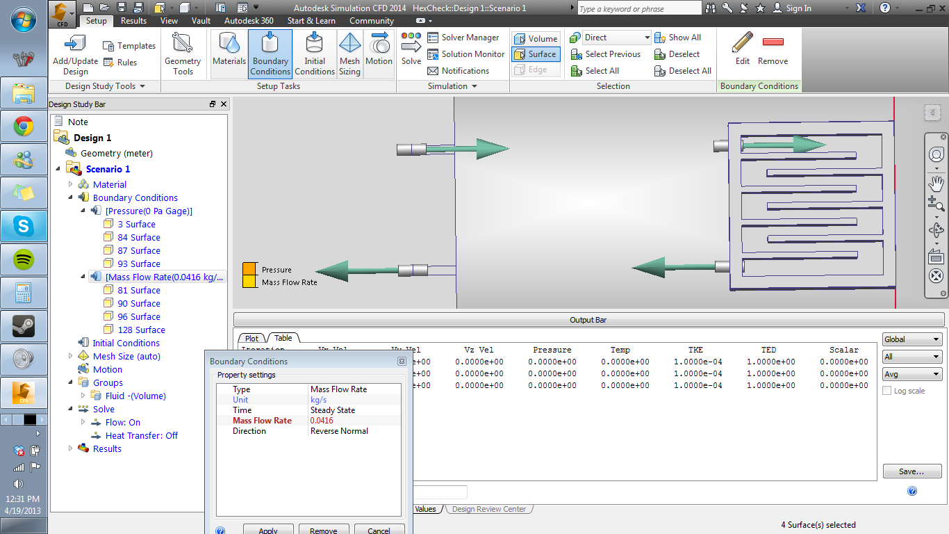
I was wondering if anyone had any tips or best-practices for simulating internal recirculating flow with the CFD package. I'm optimizing a simple exchanger + peltier block for my heat transfer class, but no matter how I assign boundrary conditions I can't seem to get my fluid volume to flow.
So far i've tried the following approaches:
Let inventor export directly to CFD. CFD correctly detects and creates the internal surface.
Let inventor export to Fusion, cap all ports, assign mass flow BCs to each capped port with corresponding zero-pressure BCs on the outlet. Although this internal surface is segemented into many pieces instead of just one continous piece like the direct-export approach does.
Both approaches yield the same result wether transient or steady-state so i'm really scratching my head at how to proceed. I've checked the wiki but it doesn't seem to have much reference on how to best set BCs between parts.
I've attached an image of my current mass-flow BCs and the full assembly. This is using the second approach.
Either way, when evaluating the model CFD detects "0 inlets, 0 outlets, 0 unknown"
Solved! Go to Solution.
Solved by Royce_adsk. Go to Solution.
Solved by Royce_adsk. Go to Solution.
11 REPLIES 11
Message 3 of 12
04-20-2013
06:08 AM
- Mark as New
- Bookmark
- Subscribe
- Mute
- Subscribe to RSS Feed
- Permalink
- Report
04-20-2013
06:08 AM
My guess without looking at the model is that you didn't put the boundary conditions on the external surface, but they are in the middle of the flow.
If you share you support share (.cfz) file the community can review your model.
-Royce

Royce.Abel
Technical Support Manager
If you share you support share (.cfz) file the community can review your model.
-Royce
Royce.Abel
Technical Support Manager
Message 4 of 12
04-21-2013
10:22 AM
- Mark as New
- Bookmark
- Subscribe
- Mute
- Subscribe to RSS Feed
- Permalink
- Report
04-21-2013
10:22 AM
Sorry for taking so long to get back to both of you, I've attached the .cfz below.
Message 5 of 12
04-21-2013
02:39 PM
- Mark as New
- Bookmark
- Subscribe
- Mute
- Subscribe to RSS Feed
- Permalink
- Report
04-21-2013
02:39 PM
Your intention seems to be a closed loop system. I would suggest you explore using an internal fan/pump.
The basic reason why your model doesn't work is because you have a mass flow rate assigned to a solid wall. If you suppress the mesh for the Nylon parts then you would have seen at least some sort of result.
Having variable material properties for your water is probably not necessary either.
Good luck!
Royce.Abel
Technical Support Manager
Message 6 of 12
04-21-2013
03:12 PM
- Mark as New
- Bookmark
- Subscribe
- Mute
- Subscribe to RSS Feed
- Permalink
- Report
04-21-2013
03:12 PM
Ah, thank you for the advice, and yes I am trying to emulate a closed system. I've read up on the documentation for the fan, and it looks like I would just designate one of my barbs as the fan/pump during the materials assignement phase?
Message 7 of 12
04-22-2013
05:52 AM
- Mark as New
- Bookmark
- Subscribe
- Mute
- Subscribe to RSS Feed
- Permalink
- Report
04-22-2013
05:52 AM
I would probably look at adding an extra part in the flow path that would be the shape of a hockey puck. That is the typical shape you will see this material used as.
Royce.Abel
Technical Support Manager
Royce.Abel
Technical Support Manager
Message 8 of 12
04-22-2013
05:56 AM
- Mark as New
- Bookmark
- Subscribe
- Mute
- Subscribe to RSS Feed
- Permalink
- Report
Message 9 of 12
Anonymous
in reply to:
Anonymous
04-22-2013
11:06 AM
- Mark as New
- Bookmark
- Subscribe
- Mute
- Subscribe to RSS Feed
- Permalink
- Report
04-22-2013
11:06 AM
Using the internal fan has fixed the problem. Just wanted to post this for anyone else who might have a similar problem to mine.
Message 10 of 12
04-22-2013
01:21 PM
- Mark as New
- Bookmark
- Subscribe
- Mute
- Subscribe to RSS Feed
- Permalink
- Report
Message 11 of 12
08-10-2013
04:10 PM
- Mark as New
- Bookmark
- Subscribe
- Mute
- Subscribe to RSS Feed
- Permalink
- Report
08-10-2013
04:10 PM
Is there any reason that we can't simulate a closed loop system?
Would it be possible to have the input = output with the input pressure/temperature/etc being set by the previous iterations calculated outlet pressure/temp/etc? Perhaps this outlet pressure could be applied to the inlet only after flow has stabilized, etc.
The internal fan/pump and heat exchangers seems a little kludgey for closed loop work...
Message 12 of 12
08-15-2013
01:05 PM
- Mark as New
- Bookmark
- Subscribe
- Mute
- Subscribe to RSS Feed
- Permalink
- Report
08-15-2013
01:05 PM
Hi,
There is no method at the moment to have a outlet drive an inlet somewhere else in the model.
I have seen some great simulation with the heat exchanger and internal fans used for closed loop systems.
What do you consider 'kludgey' about the workflow?
-Royce
Royce.Abel
Technical Support Manager
Reply
Topic Options
- Subscribe to RSS Feed
- Mark Topic as New
- Mark Topic as Read
- Float this Topic for Current User
- Bookmark
- Subscribe
- Printer Friendly Page
Forums Links
Can't find what you're looking for? Ask the community or share your knowledge.
Post to forums
