Community
CFD Forum
Welcome to Autodesk’s CFD Forums. Share your knowledge, ask questions, and explore popular CFD topics.
Turn on suggestions
Auto-suggest helps you quickly narrow down your search results by suggesting possible matches as you type.
Reply
Topic Options
- Subscribe to RSS Feed
- Mark Topic as New
- Mark Topic as Read
- Float this Topic for Current User
- Bookmark
- Subscribe
- Printer Friendly Page
Message 1 of 15
03-24-2014
09:36 AM
- Mark as New
- Bookmark
- Subscribe
- Mute
- Subscribe to RSS Feed
- Permalink
- Report
03-24-2014
09:36 AM
Hello,
I'm trying to simulate the working of a fountain, using Autodesk Simulation CFD 2014.
I've already designed the fountain in Inventor 2014.
But I don't know how I can create the internal volume for this?
Or does anyone has a good tutorial for this?
Thanks
Solved! Go to Solution.
Solved by Jon.Wilde. Go to Solution.
14 REPLIES 14
Message 2 of 15
03-24-2014
12:18 PM
- Mark as New
- Bookmark
- Subscribe
- Mute
- Subscribe to RSS Feed
- Permalink
- Report
03-24-2014
12:18 PM
Is there an internal volume or is this going to overflow?
Jon Wilde
Technical Support Manager
CFD Knowledge Network | CFD Help | My Screencasts | Autodesk Simuation YouTube | CFD Tutorials
Message 3 of 15
03-24-2014
12:36 PM
- Mark as New
- Bookmark
- Subscribe
- Mute
- Subscribe to RSS Feed
- Permalink
- Report
03-24-2014
12:36 PM
It's going to overflow.
So the water will go through the pump, in to the tubes & let it overflow at the top.
So the water will go through the pump, in to the tubes & let it overflow at the top.
Message 4 of 15
03-24-2014
01:01 PM
- Mark as New
- Bookmark
- Subscribe
- Mute
- Subscribe to RSS Feed
- Permalink
- Report
03-24-2014
01:01 PM
OK so there is no internal volume as such, this is a free surface analysis. Fill the water as high as you need it initially (with a part in CAD), then pump more in through some sort of inlet beneath.
Also model an air domain, which is actually going to be meshed and needs to be meshed really well where the water will fall. You will actually set the air to be a water material, all is explained in the guide.
This Free Surface link should contain all you need.
Please post some images once it is working!
Jon
Jon Wilde
Technical Support Manager
CFD Knowledge Network | CFD Help | My Screencasts | Autodesk Simuation YouTube | CFD Tutorials
Message 5 of 15
03-25-2014
12:04 PM
- Mark as New
- Bookmark
- Subscribe
- Mute
- Subscribe to RSS Feed
- Permalink
- Report
03-25-2014
12:04 PM
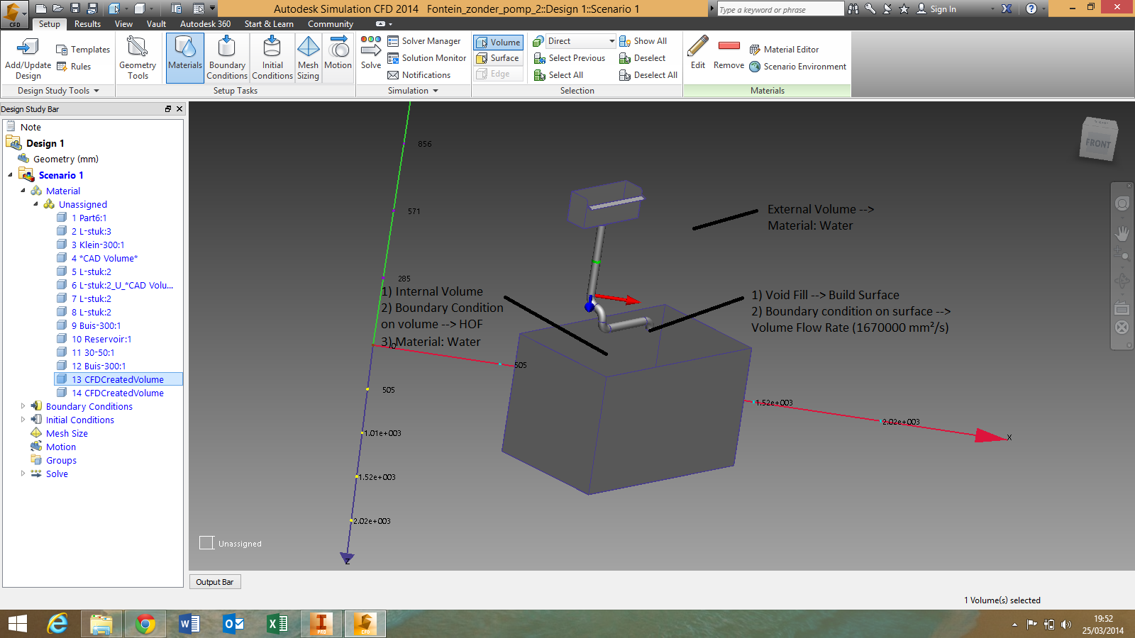
Well I've been trying by using the tutorial to get the fountain to work, but I think I'm doing something wrong because I can't mesh it.
I'm completely new to this program, but I need to use it for a project in the university.
Everything I've done is in de screenshot below.
Thank you for the fast replies!
Message 6 of 15
03-25-2014
12:20 PM
- Mark as New
- Bookmark
- Subscribe
- Mute
- Subscribe to RSS Feed
- Permalink
- Report
03-25-2014
12:20 PM
Hi!
Would you be willing to post your CAD file so we can show you what you need to modify? Easier to just show sometimes and would be a good learning opportunity for the forum community.
Thanks!
Royce.Abel
Technical Support Manager
Message 7 of 15
03-25-2014
12:39 PM
- Mark as New
- Bookmark
- Subscribe
- Mute
- Subscribe to RSS Feed
- Permalink
- Report
03-25-2014
12:39 PM
I've added the CAD files in the attachements.
I have a simplified model (without the pump and wall) and a complete model.
I've created the simplified model to make the simulation easier, but in the end I also want to simulate the complete model.
Message 8 of 15
03-28-2014
05:34 AM
- Mark as New
- Bookmark
- Subscribe
- Mute
- Subscribe to RSS Feed
- Permalink
- Report
03-28-2014
05:34 AM
I still can't get it to work..
Does somebody has an idea on what I have to change on my CAD-model?
Message 9 of 15
03-28-2014
05:54 AM
- Mark as New
- Bookmark
- Subscribe
- Mute
- Subscribe to RSS Feed
- Permalink
- Report
03-28-2014
05:54 AM
Hi Dimitri,
You need to model the air that the water will be within also - did you have a chance to read the guide that was posted?
Something like this. Then we can just make the water inlet here.

The model would be set up with everything suppressed apart from the volume - which we call 'water' but as we do not assign a Height Of Fluid Initial Condition to it, this will act as air initially.
At the back we have a flow rate where the water will enter (I guessed 10 l/min) and I also left a P=0 on the very top.
Use a refinement region or similar where the water will flow

Turn on Free Surface and set the Gravity direction. Turning on the free surface will ensure that water enters at the condition we applied at the rear.
Once you switch this on, the solution will switch to transient, this is fine. We may need to reduce the timestep size but try it as is for now.
This is it meshed, with the suppressed parts turned back on and shaded. I also right clicked to show the Free Surface - which is just about entering the pipe at the rear.

We will likely need more mesh but I will leave that to you.
Does that help?
Jon
Jon Wilde
Technical Support Manager
CFD Knowledge Network | CFD Help | My Screencasts | Autodesk Simuation YouTube | CFD Tutorials
Message 10 of 15
03-28-2014
07:45 AM
- Mark as New
- Bookmark
- Subscribe
- Mute
- Subscribe to RSS Feed
- Permalink
- Report
03-28-2014
07:45 AM
Starting to fill, I do think it needs more (and really more localised) mesh but this should run OK

Jon Wilde
Technical Support Manager
CFD Knowledge Network | CFD Help | My Screencasts | Autodesk Simuation YouTube | CFD Tutorials
Message 11 of 15
04-04-2014
10:33 AM
- Mark as New
- Bookmark
- Subscribe
- Mute
- Subscribe to RSS Feed
- Permalink
- Report
04-04-2014
10:33 AM
I have on more question.
How did you create the fluid volume?
Did you use Inventor Fusion/Professional or a built-in feature of Simulation CFD ?
Message 12 of 15
04-04-2014
10:53 AM
- Mark as New
- Bookmark
- Subscribe
- Mute
- Subscribe to RSS Feed
- Permalink
- Report
04-04-2014
10:53 AM
I used Inventor and just drew a cuboid 🙂
You can use any method, if you bring solid overlapping parts through, CFD will break them into sections, if it is hollow and sealed, CFD will fill it with a fluid volume automaticaly.
Jon Wilde
Technical Support Manager
CFD Knowledge Network | CFD Help | My Screencasts | Autodesk Simuation YouTube | CFD Tutorials
Message 13 of 15
04-04-2014
11:36 AM
- Mark as New
- Bookmark
- Subscribe
- Mute
- Subscribe to RSS Feed
- Permalink
- Report
04-04-2014
11:36 AM
Oke thanks!
I've tried to make it on my own on an updated model. I just made 2 extra parts that respresent the fluid volume with inventor.
I've also meshed it more locally with 2 refinement boxes. but now I get the error that surface 201 can't be meshed?
What am I doing wrong?
Here is a link to my dropbox folder:
Message 14 of 15
04-04-2014
02:51 PM
- Mark as New
- Bookmark
- Subscribe
- Mute
- Subscribe to RSS Feed
- Permalink
- Report
04-04-2014
02:51 PM
Check out the surface meshing diagnostics, your CAD change appears to have introduced a very thin surface. Tidy that up and this should mesh OK.
Jon Wilde
Technical Support Manager
CFD Knowledge Network | CFD Help | My Screencasts | Autodesk Simuation YouTube | CFD Tutorials
Message 15 of 15
04-06-2014
06:05 AM
- Mark as New
- Bookmark
- Subscribe
- Mute
- Subscribe to RSS Feed
- Permalink
- Report
Reply
Topic Options
- Subscribe to RSS Feed
- Mark Topic as New
- Mark Topic as Read
- Float this Topic for Current User
- Bookmark
- Subscribe
- Printer Friendly Page
