Community
- Forums Home
- >
- CFD Community
- >
- CFD Forum
- >
- Re: Help me understand why inlet size affects the results so much
CFD Forum
Welcome to Autodesk’s CFD Forums. Share your knowledge, ask questions, and explore popular CFD topics.
Turn on suggestions
Auto-suggest helps you quickly narrow down your search results by suggesting possible matches as you type.
Reply
Topic Options
- Subscribe to RSS Feed
- Mark Topic as New
- Mark Topic as Read
- Float this Topic for Current User
- Bookmark
- Subscribe
- Printer Friendly Page
Message 1 of 12
09-04-2012
01:56 AM
- Mark as New
- Bookmark
- Subscribe
- Mute
- Subscribe to RSS Feed
- Permalink
- Report
09-04-2012
01:56 AM
Help me understand why inlet size affects the results so much
So, I'm designing what is basically a water condenser i.e. humid air (steam) gets condensed into water. It consists of an inlet, condensing chamber and an outlet. On top it has cooling fins and is made of aluminium. The whole object is about 200mm in size. Steam/humid air enters through the inlet, condenses and comes out the outlet with a percentage of it as liquid.
When the inlet was a 20mm round hole, it performed much better than when the inlet was a wide (around 180mm) slot-like hole. I don't have the exact numbers now, but the percentage of liquid was around 15% more with the small inlet than with the large one and the outlet temperature was a lot lower. The volume flow rate, temperature and humidity of the inlet were the same on both occasions. Just the inlet size varied.
I tried running it with both laminar and turbulent flow and the difference was still there.
I can't wrap my brain around why the smaller inlet performs better even though the volume flow is the same. the only thing that I can think of is that the larger inlet also heats the base more (which doesn't have cooling fins attached).
Any one have ideas?
11 REPLIES 11
Message 2 of 12
09-05-2012
12:06 AM
- Mark as New
- Bookmark
- Subscribe
- Mute
- Subscribe to RSS Feed
- Permalink
- Report
09-05-2012
12:06 AM
How about the pressure drop? What does this look like when the area changes from small to large vs design 2?
Jon Wilde
Technical Support Manager
CFD Knowledge Network | CFD Help | My Screencasts | Autodesk Simuation YouTube | CFD Tutorials
Message 3 of 12
09-05-2012
03:58 AM
- Mark as New
- Bookmark
- Subscribe
- Mute
- Subscribe to RSS Feed
- Permalink
- Report
09-05-2012
03:58 AM
Inlet bulk pressure on small inlet is 5,629 Pa, on the large inlet it is 4,835 Pa.
Outlet-inlet delta Reynold's number is 69,511 for the design with the small inlet and 183,02 for the design with the large inlet.
Message 4 of 12
09-10-2012
06:07 AM
- Mark as New
- Bookmark
- Subscribe
- Mute
- Subscribe to RSS Feed
- Permalink
- Report
09-10-2012
06:07 AM
Is that meant to read 69.5k and 18k?
Jon Wilde
Technical Support Manager
CFD Knowledge Network | CFD Help | My Screencasts | Autodesk Simuation YouTube | CFD Tutorials
Message 5 of 12
09-10-2012
06:45 AM
- Mark as New
- Bookmark
- Subscribe
- Mute
- Subscribe to RSS Feed
- Permalink
- Report
Message 6 of 12
09-10-2012
06:59 AM
- Mark as New
- Bookmark
- Subscribe
- Mute
- Subscribe to RSS Feed
- Permalink
- Report
09-10-2012
06:59 AM
Ah, OK, so in both cases the Reynolds number is very small, laminar flow.
So, it is highly unlikely that what I initially suspected as the cause has any bearing here. I think you may be right with your initial conclusion, without being fully able to picture the scenario of course. Feel free to share some images if you are happy to
Jon Wilde
Technical Support Manager
CFD Knowledge Network | CFD Help | My Screencasts | Autodesk Simuation YouTube | CFD Tutorials
Message 7 of 12
09-10-2012
07:45 AM
- Mark as New
- Bookmark
- Subscribe
- Mute
- Subscribe to RSS Feed
- Permalink
- Report
09-10-2012
07:45 AM
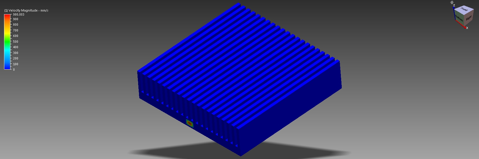
I've attached 3 pictures. One is the full design so you can see the cooling fins. The other two are of the internal volume with global static pressure; one with the small inlet, one with the wide inlet. Please refer to the viewcube for the orientation (full is from above, internal volumes from below).
Message 8 of 12
09-11-2012
07:38 AM
- Mark as New
- Bookmark
- Subscribe
- Mute
- Subscribe to RSS Feed
- Permalink
- Report
09-11-2012
07:38 AM
I see, how are you setting this up? Is the steam modelled with a table to take into account the condensation? By the way, if there is a lot of this, we may be off with the thermal results as we cannot model 2 phase..
Jon Wilde
Technical Support Manager
CFD Knowledge Network | CFD Help | My Screencasts | Autodesk Simuation YouTube | CFD Tutorials
Message 9 of 12
09-11-2012
11:49 AM
- Mark as New
- Bookmark
- Subscribe
- Mute
- Subscribe to RSS Feed
- Permalink
- Report
09-11-2012
11:49 AM
The internal volume is moist air with variable environment. The cooling fins have film coefficient on them. Inlet is set up with volume flow rate, 98C temperature and humidity of 1. Outlet has just pressure.
For some reason, the solver didn't like temperature any higher than 98C.
I don't know if that is the right way to do it. The help/wiki wasn't too clear on when to use steam and when to use humd air. In any case, I didn't get steam working because the solver quits unexpectedly.
Message 10 of 12
09-18-2012
03:01 AM
- Mark as New
- Bookmark
- Subscribe
- Mute
- Subscribe to RSS Feed
- Permalink
- Report
09-18-2012
03:01 AM
Sounds like it should be OK, so long as this is just humid air and not steam. If steam, make the switch and run with steam (superheated) fluid. You would need to set a steam quality at the inlet and turn on steam in the physics.
Jon Wilde
Technical Support Manager
CFD Knowledge Network | CFD Help | My Screencasts | Autodesk Simuation YouTube | CFD Tutorials
Message 11 of 12
09-21-2012
08:03 AM
- Mark as New
- Bookmark
- Subscribe
- Mute
- Subscribe to RSS Feed
- Permalink
- Report
09-21-2012
08:03 AM
Thanks for the help so far.
I have done some testing with different models etc. and I've found out that even though the Reynolds numbers are low, turbulence plays a big part in why the small inlet peforms better. There are other factors at play too, but not as much as the turbulence.
What type of turbulence model should I be using with these simulations? K-epsilon isn't stable but eddy viscosity and low Re k-eps seem to be stable. Also, is advection scheme 1 suitable for such a simulation or should I try others?
Message 12 of 12
10-15-2012
08:05 AM
- Mark as New
- Bookmark
- Subscribe
- Mute
- Subscribe to RSS Feed
- Permalink
- Report
10-15-2012
08:05 AM
Apologies for the delay here, only just noticed page 2.
You could try low re-ke, ADV1 should be OK. Maybe try 5 also, but I suspect it would yield the same results
Jon Wilde
Technical Support Manager
CFD Knowledge Network | CFD Help | My Screencasts | Autodesk Simuation YouTube | CFD Tutorials
Reply
Topic Options
- Subscribe to RSS Feed
- Mark Topic as New
- Mark Topic as Read
- Float this Topic for Current User
- Bookmark
- Subscribe
- Printer Friendly Page
