Community
CFD Forum
Welcome to Autodesk’s CFD Forums. Share your knowledge, ask questions, and explore popular CFD topics.
Turn on suggestions
Auto-suggest helps you quickly narrow down your search results by suggesting possible matches as you type.
Reply
Topic Options
- Subscribe to RSS Feed
- Mark Topic as New
- Mark Topic as Read
- Float this Topic for Current User
- Bookmark
- Subscribe
- Printer Friendly Page
Message 1 of 5
01-14-2013
06:58 PM
- Mark as New
- Bookmark
- Subscribe
- Mute
- Subscribe to RSS Feed
- Permalink
- Report
01-14-2013
06:58 PM
Different results for the same part and conditions
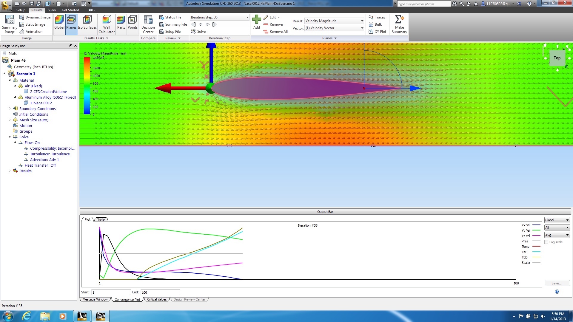
I have attached an Inventor ipt and two jpegs. I have tried to follow the online tutorial. When I ran an airfoil with an inlet velocity of 45 mph and an outlet pressure of 0 psi it wouldn't run but 5 iterations. When I ran it again with an inlet velocity of 45 mph and an outlet velocity of -45 mph and an outlet pressure of 0 psi it ran for 100 iterations and I think I saved that. When I reopened the thing I saved it was at 35 iterations and I couldn't figure out how to start it up again to get back to the full 100 iterations. I saved a jpeg of the velocity vectors. Notice the "X"'s and "V"'s that appear in front of the airfoil. I don't know what they are.
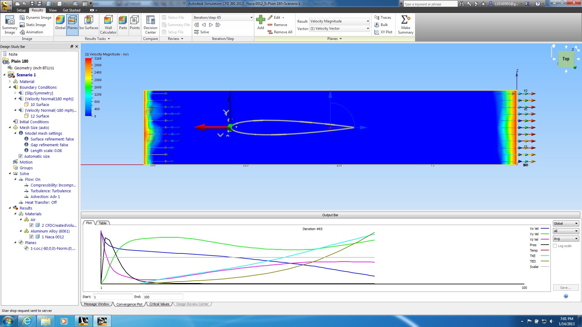
I then ran everything the same but at 180 mph in and out. It ran for 65 iterations but the velocity vectors, as seen in the second jpeg aren't right. Again the "X"'s and "V"'s appear. I tried running it again and it didn't "solve" at all.
Is it possible that something is corrupt with the ipt? I did a sketch using an equation and it was a bit flaky.
I notice the false readings in the mesh browser. Do I need to make regions and refine the mesh?
This is my first try at CFD and I haven't read much besides the online tutorial.
Any help would be appreciated.
4 REPLIES 4
Message 2 of 5
01-15-2013
01:33 AM
- Mark as New
- Bookmark
- Subscribe
- Mute
- Subscribe to RSS Feed
- Permalink
- Report
01-15-2013
01:33 AM
It sounds as though you are over constraining the model.
Only assign one flow rate and one pressure condition for wind tunnel analyses, typically a flow rate at the inlet and presure at the outlet.
Try running with mesh adaption, this will help capture the flow better. Also use Advection Scheme 5 (check out the help) for improved results accuracy in external aero.
Jon Wilde
Technical Support Manager
CFD Knowledge Network | CFD Help | My Screencasts | Autodesk Simuation YouTube | CFD Tutorials
Message 3 of 5
01-15-2013
03:59 AM
- Mark as New
- Bookmark
- Subscribe
- Mute
- Subscribe to RSS Feed
- Permalink
- Report
01-15-2013
03:59 AM
If the external volume box were a wind tunnel would there slip/symmetry constraints on the sides? The wind tunnel does have walls. That is the reasoning I used for those boundary conditions. I am not arguing. Just trying to understand boundary conditions. I will do as suggested to see if it works.
When having adaptive meshing what does the 3 in the dialogue box mean? Does the mesh adapt on the first 3 iterations or does it adapt every third iteration?
I had troubles with Falcon for Inventor and the standalone Falcon. Autodesk has been prompt at replying to emails. I am happy with Autodesk. Chagrined with my stupidity.
Message 4 of 5
01-15-2013
07:02 PM
- Mark as New
- Bookmark
- Subscribe
- Mute
- Subscribe to RSS Feed
- Permalink
- Report
01-15-2013
07:02 PM
Hi, I believe that the 3 (Cycles to Run) that you refer to means that the software will refine the mesh three times. Each refinement will happen after the solution has converged or has finished its specified number of iterations. It would be like having three additional design scenarios analysed by the software.
Message 5 of 5
01-16-2013
12:45 AM
- Mark as New
- Bookmark
- Subscribe
- Mute
- Subscribe to RSS Feed
- Permalink
- Report
01-16-2013
12:45 AM
The slip/symm on the walls is up to you, it will work with them for sure but it depends what you are modelling.
When having adaptive meshing what does the 3 in the dialogue box mean? Does the mesh adapt on the first 3 iterations or does it adapt every third iteration?
ilyas is correct, CFD will run a solution and converge, then it will refine (and coarsen if allowed) the mesh where needed. Then it will run again. This will be repeated a further 2 times if you have 3 cycles assigned.
Glad you are pleased with our support and are using our products too!
Kind regards,
Jon
Jon Wilde
Technical Support Manager
CFD Knowledge Network | CFD Help | My Screencasts | Autodesk Simuation YouTube | CFD Tutorials
Reply
Topic Options
- Subscribe to RSS Feed
- Mark Topic as New
- Mark Topic as Read
- Float this Topic for Current User
- Bookmark
- Subscribe
- Printer Friendly Page
