Community
- Forums Home
- >
- Robot Structural Analysis Products Community
- >
- Robot Structural Analysis Forum
- >
- Re: wrong load on panel
Robot Structural Analysis Forum
Welcome to Autodesk’s Robot Structural Analysis Forums. Share your knowledge, ask questions, and explore popular Robot Structural Analysis topics.
Turn on suggestions
Auto-suggest helps you quickly narrow down your search results by suggesting possible matches as you type.
Reply
Topic Options
- Subscribe to RSS Feed
- Mark Topic as New
- Mark Topic as Read
- Float this Topic for Current User
- Bookmark
- Subscribe
- Printer Friendly Page
Message 1 of 19
06-13-2011
01:49 AM
- Mark as New
- Bookmark
- Subscribe
- Mute
- Subscribe to RSS Feed
- Permalink
- Report
06-13-2011
01:49 AM
Hello,
I have a problem applying hydrostatic load on two manual meshed panels.....it is not the first time I have this problem.
Local axis for panel and f.e. are the same, not the load??!!!
Any advice??.....perhaps a bug to be solved for 2012 release??
Bye
Roberto
Solved! Go to Solution.
Solved by Artur.Kosakowski. Go to Solution.
18 REPLIES 18
Message 2 of 19
06-13-2011
01:53 AM
- Mark as New
- Bookmark
- Subscribe
- Mute
- Subscribe to RSS Feed
- Permalink
- Report
Message 3 of 19
06-13-2011
02:52 AM
- Mark as New
- Bookmark
- Subscribe
- Mute
- Subscribe to RSS Feed
- Permalink
- Report
06-13-2011
02:52 AM
Roberto,
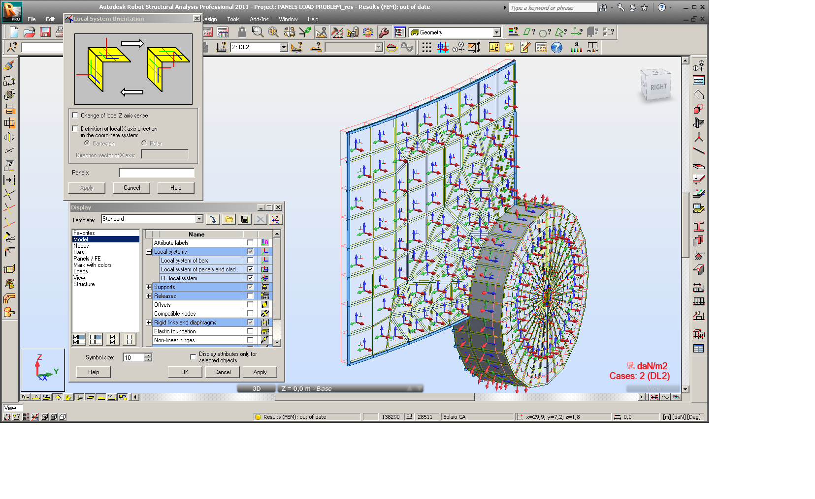
I have used the Local (panel) system orientation dialog to set the right orientation of both local X (0,0,1) and Z axis for the vertical 'wall' of the structure to make sure the load is correctly applied.
Regards,
Artur Kosakowski
Message 4 of 19
06-13-2011
04:59 AM
- Mark as New
- Bookmark
- Subscribe
- Mute
- Subscribe to RSS Feed
- Permalink
- Report
06-13-2011
04:59 AM
Artur,
many thanks for your reply.
You have to consider that me too have used the dialog set to orient the panel in direction 0,0,1 but sometimes, apparently without any reason, axis exchange their local direction with strange behaviour on hydro load (sometimes different behaviour before and after calculation)
The two added images are taken from your correct model......I think you can agree with me that it is a little strange.
Take in mind that with other more complex models (generated with copy and paste option from more Robot session at the same time) I had to fight a lot to have exactly the correct axis and load direction, and you well known the amount of hours I spent with Robot..... I'm sure you can understand that in my honest opinion this is a problem that need to be solved in the next version.
Bye
Roberto
Message 5 of 19
06-13-2011
05:12 AM
- Mark as New
- Bookmark
- Subscribe
- Mute
- Subscribe to RSS Feed
- Permalink
- Report
06-13-2011
05:12 AM
Roberto,
There is nothing wrong with both displays you shown. You simply compare two set of information. If you display local axis of surface elements without displaying local axis of panels you see the directions of surface elements as generated during meshing (in such case the direction of the local X axes of a particular surface element is governed by order in which its nodes have been created). If you display both elements and panels local axis, the prior are shown in the way they are set for model calculations (direction of the local X axes of a panel is used to set the directions of each of element of the mesh generated for this panel). In fact display of local axis of surface elements only is of limited use for Robot users and they should display both attributes at the same time.
I hope this clarifies this issue.
Regards,
Artur Kosakowski
Message 6 of 19
06-13-2011
05:39 AM
- Mark as New
- Bookmark
- Subscribe
- Mute
- Subscribe to RSS Feed
- Permalink
- Report
06-13-2011
05:39 AM
Artur,
ok for the clarification, but consider that even if I use the dialog set to re-orient the vertical part of the model according to 0,0,1 vector (for x axes, because z is ok) I have not the correct load direction for those two panel.....what exactly have you done (step by step) please??
Many thanks
Roberto
Message 7 of 19
06-13-2011
06:12 AM
- Mark as New
- Bookmark
- Subscribe
- Mute
- Subscribe to RSS Feed
- Permalink
- Report
06-13-2011
06:12 AM
Roberto,
1. Select panels 1 and 2 (the ones with the opposite load directions)
2. Set their local X axis directions as 0,0,1
3. Select panels 1 and 2 again and run local mesh generation for these panels
4. Change load case selection from case 2 to case 1 and to case 2 again to refresh the display
In case you need further help with your case create a service request using the subscription site.
Regards,
Artur Kosakowski
Message 8 of 19
06-13-2011
06:50 AM
- Mark as New
- Bookmark
- Subscribe
- Mute
- Subscribe to RSS Feed
- Permalink
- Report
Message 9 of 19
05-31-2012
01:09 PM
- Mark as New
- Bookmark
- Subscribe
- Mute
- Subscribe to RSS Feed
- Permalink
- Report
05-31-2012
01:09 PM
Hi I am having a very strange problem with load direction on panels using hydrostatic load(in MATERIAL UPSET load case, LC 9). the load is applied properly and is properly shown. after running it switched the direction if i press on the "show load value description". also I do not know why the local axis of the generated finite element is different than that of the panel, I think they should be the same.
attached are the files showing my problem..please help!!
Message 10 of 19
06-01-2012
09:27 AM
- Mark as New
- Bookmark
- Subscribe
- Mute
- Subscribe to RSS Feed
- Permalink
- Report
06-01-2012
09:27 AM
The reason of strange effects you observed was opposite local Z direction for panel 594 than for finite elements contained in it - see the screen capture below:

The source of it was in panel slightly non-planar (twisted). After correcting it and remeshing the panels local Z directions are coherent. The effect you observed concerning the display and application of hydrostatic loads is not observed too. Attached corrected model.
Regards,
Pawel Pulak
Technical Account Specialist
Message 11 of 19
06-01-2012
10:10 AM
- Mark as New
- Bookmark
- Subscribe
- Mute
- Subscribe to RSS Feed
- Permalink
- Report
06-01-2012
10:10 AM
Thanks for the clarification Pawel, but should the load be reversed when the Z-axis of the panel is reversed? even if it is not planer? or the program does not understand that?
Also how to make sure that the panel is planer or how to fix that or check that?
Thanks
Message 12 of 19
06-04-2012
01:33 AM
- Mark as New
- Bookmark
- Subscribe
- Mute
- Subscribe to RSS Feed
- Permalink
- Report
06-04-2012
01:33 AM
After changing local Z of the panel the load will be reversed but for your original file the effect of opposite load direction with/without description will still be observed - because of no planarity of panel resulting in opposite Z for finite elements than for panel.
The sensitivity to such small planarity inaccuracies was reported to developement team to be analyzed and eliminated.
Planarity can be corrected:
1/ or correcting to plane from Edit>Detailed correct

2/ or extending the number of decimals and correcting coordinates of some points of contour

Regards,
Pawel Pulak
Technical Account Specialist
Message 13 of 19
06-04-2012
10:47 AM
- Mark as New
- Bookmark
- Subscribe
- Mute
- Subscribe to RSS Feed
- Permalink
- Report
Message 14 of 19
06-04-2012
06:55 PM
- Mark as New
- Bookmark
- Subscribe
- Mute
- Subscribe to RSS Feed
- Permalink
- Report
06-04-2012
06:55 PM
or use Rafals' add in.....................
Message 15 of 19
06-05-2012
01:15 AM
- Mark as New
- Bookmark
- Subscribe
- Mute
- Subscribe to RSS Feed
- Permalink
- Report
06-05-2012
01:15 AM
Tony,
kudos for adding this info 🙂
Using "rounding add-in" of Rafal results in bigger "curving" of panel instead of "flattening" it but it helps too.
The effect noticed by mgaafar can be observed for some range of panel unplanarity.
Regards,
Pawel Pulak
Technical Account Specialist
Message 16 of 19
06-05-2012
08:00 AM
- Mark as New
- Bookmark
- Subscribe
- Mute
- Subscribe to RSS Feed
- Permalink
- Report
06-05-2012
08:00 AM
Since almost no one works with warped panels, I think there should be an option that checks all panels if they are planer or not and then fix the warped ones automatically instead of checking and fixing panel by panel.
Message 17 of 19
06-05-2012
12:04 PM
- Mark as New
- Bookmark
- Subscribe
- Mute
- Subscribe to RSS Feed
- Permalink
- Report
06-05-2012
12:04 PM
Hi Pawel,
consider that I had this problem (you can see the first post) more than one time and apparently in a random manner applying hydrostatic load on curved shell.......sometimes is not possible to flatten a cylindrical tank!!!!
Bye
Roberto
Message 18 of 19
06-06-2012
01:45 AM
- Mark as New
- Bookmark
- Subscribe
- Mute
- Subscribe to RSS Feed
- Permalink
- Report
06-06-2012
01:45 AM
Hi Roberto,
I agree that it should not be necessary to eliminate any planarity inaccuracies - especially that sometimes (slightly twisted roofs, intersections of cylinders, etc) they cannot be avoided.
As I have mentioned in my previous answer:
"The sensitivity to such small planarity inaccuracies was reported to developement team to be analyzed and eliminated."
Regards,
Pawel Pulak
Technical Account Specialist
Message 19 of 19
06-06-2012
05:03 AM
- Mark as New
- Bookmark
- Subscribe
- Mute
- Subscribe to RSS Feed
- Permalink
- Report
Reply
Topic Options
- Subscribe to RSS Feed
- Mark Topic as New
- Mark Topic as Read
- Float this Topic for Current User
- Bookmark
- Subscribe
- Printer Friendly Page
Forums Links
Can't find what you're looking for? Ask the community or share your knowledge.
Post to forums
