Community
- Forums Home
- >
- Robot Structural Analysis Products Community
- >
- Robot Structural Analysis Forum
- >
- Re: tutorial or example for machine foundation
Robot Structural Analysis Forum
Welcome to Autodesk’s Robot Structural Analysis Forums. Share your knowledge, ask questions, and explore popular Robot Structural Analysis topics.
Turn on suggestions
Auto-suggest helps you quickly narrow down your search results by suggesting possible matches as you type.
tutorial or exaple for machine foundation
17 REPLIES 17
SOLVED
Reply
Topic Options
- Subscribe to RSS Feed
- Mark Topic as New
- Mark Topic as Read
- Float this Topic for Current User
- Bookmark
- Subscribe
- Printer Friendly Page
Message 1 of 18
Anonymous
5473 Views, 17 Replies
07-11-2012
06:54 AM
- Mark as New
- Bookmark
- Subscribe
- Mute
- Subscribe to RSS Feed
- Permalink
- Report
07-11-2012
06:54 AM
Does anyone have a tutorial or example for RSA, how to design concrete blocks or pedestals for steam or gas turbines or smth similar. Modal,time history analysis or harmonis (FRF), how to apply the dynamic forces that act in the neutral axisof the turbine which is above the foundations, what load combinations to use, what type of mashing is the best chooise in this case.
Anything that can be helpfull.
Thanks
Solved! Go to Solution.
Solved by Pawel.Pulak. Go to Solution.
Solved by Pawel.Pulak. Go to Solution.
Solved by Pawel.Pulak. Go to Solution.
17 REPLIES 17
Message 2 of 18
07-12-2012
04:55 AM
- Mark as New
- Bookmark
- Subscribe
- Mute
- Subscribe to RSS Feed
- Permalink
- Report
07-12-2012
04:55 AM
Try this one for time history
tony
Message 3 of 18
07-12-2012
05:56 AM
- Mark as New
- Bookmark
- Subscribe
- Mute
- Subscribe to RSS Feed
- Permalink
- Report
07-12-2012
05:56 AM
Additional explanations to link provided by Tony:
1/ depending on soil data and necessity to consider deformation of foundation or treating it as rigid body it is possible to model it as
- node with added mass and elastic support
- panel on elastic supports
- solid on elastic supports
2/ eccentricity between foundation and turbine can be modeled using rigid links
---------------------------------------------
If this post answers your question please click "Accept as Solution". It will help everyone to find answer more quickly!
Regards,
Pawel Pulak
Technical Account Specialist
Message 4 of 18
07-12-2012
06:14 AM
- Mark as New
- Bookmark
- Subscribe
- Mute
- Subscribe to RSS Feed
- Permalink
- Report
07-12-2012
06:14 AM
Thank you for the answer,
can you please show in a picture or I a small model how to model the eccentricities with rigid links?
Thanks
Message 5 of 18
07-12-2012
08:59 AM
- Mark as New
- Bookmark
- Subscribe
- Mute
- Subscribe to RSS Feed
- Permalink
- Report
07-12-2012
08:59 AM
The screen capture below shows some example when modeling by solid. Top (master) node corresponds to the center of mass of the turbine. Bottom nodes correspond to the connection of the turbine with the block. Of course the distribution of these nodes corresponds to real geometry of turbine and details of connection.

In case of rigid links connected to solid it will be necessary to activate RLINK algorithm for rigid links in Job Preferences>Structure Analysis
---------------------------------------------
If this post answers your question please click "Accept as Solution". It will help everyone to find answer more quickly!
Regards,
Pawel Pulak
Technical Account Specialist
Message 6 of 18
07-18-2012
06:28 AM
- Mark as New
- Bookmark
- Subscribe
- Mute
- Subscribe to RSS Feed
- Permalink
- Report
07-18-2012
06:28 AM
Mr. Pulak,
I am trying to model the following as in picture 1, as you explained in the previous email, and I am getting the following error,picture 2. What am I doing wrong?
Thanks
Message 7 of 18
07-18-2012
07:11 AM
- Mark as New
- Bookmark
- Subscribe
- Mute
- Subscribe to RSS Feed
- Permalink
- Report
07-18-2012
07:11 AM
Solid elements have no degrees of freedom (stiffness) in rotation. So if you have defined rigid links with only pairs of nodes (one master and one slave) these rigid links can rotate about nodes belonging to solids - at the bottom ends of rigid links shown on your screen capture.
One of the methods to avoid it is to define rigid links with at least 3 non-collinear slave nodes to connect to solid in 3 points - like below:

---------------------------------------------
If this post answers your question please click "Accept as Solution". It will help everyone to find answer more quickly!
Regards,
Pawel Pulak
Technical Account Specialist
Message 8 of 18
07-23-2012
02:31 AM
- Mark as New
- Bookmark
- Subscribe
- Mute
- Subscribe to RSS Feed
- Permalink
- Report
07-23-2012
02:31 AM
Hi,
how can isolated nodes with attributes be included in the mesh? I am trying with Emitters, but no luck, is there a meshing option that includes all nodes where node forces are applied before meshing?
And also getting the following warning:It is neccesary to divide tapered bar to calculation elements for nonlinear analysis.
What does it mean? since i have no bars in the model ( its a concrete block) and how can it it be done?
Thanks
Message 9 of 18
07-23-2012
06:53 AM
- Mark as New
- Bookmark
- Subscribe
- Mute
- Subscribe to RSS Feed
- Permalink
- Report
07-23-2012
06:53 AM
If FE mesh is not frozen it is enough to run analysis and during model generation FE mesh will be adapted to new surface nodes.
In case of local mesh generation (as in the video available there: http://screencast.com/t/tNiJTBWiZk ) FE mesh is adapted to new surface nodes for unfrozen and frozen FE meshes.
Above remarks are valid for solids meshed using standard tetrahedral FE mesh generation.
In case of mapped meshing of solids generated using extrude or revolve commands adapting mesh is not possible for side faces - but your screen capture suggests that you do not use this feature.
As concerns the warning related to tapered members it is not justified and can be ignored.
Best regards,
Pawel Pulak
Technical Account Specialist
Message 10 of 18
07-24-2012
03:55 AM
- Mark as New
- Bookmark
- Subscribe
- Mute
- Subscribe to RSS Feed
- Permalink
- Report
07-24-2012
03:55 AM
Mr Pulak,
In order to obtain a) steady state response of a concrete block on which a machine is operating with a xx frequency:
1) calculated the right modal frequencies with all dead loads converted into mass
2) calculated the dynamic forces and moments ( in phase and out of phase in all directions) acting to the centre of concrete base area, and applied these forces to this point as a new load case (in phase Y).
3) the load case (in phase Y) chanced to a harmonic analysis with excitation frequency of the machine ( 50 hz in this case)
4) results - displacement - for case 5 ( in phase Y)
b) transient amplitude
same as a) till point 2) but instead of harmonic analysis will be Harmonic (FRF) from 0.5-50 Hz ( this time for out of phase Y)
3) results- advanced- FRF tables or diagrams
Please confirm if the above steps are correct
Thanks
Message 11 of 18
07-24-2012
04:59 AM
- Mark as New
- Bookmark
- Subscribe
- Mute
- Subscribe to RSS Feed
- Permalink
- Report
07-24-2012
04:59 AM
What to you mean by transient response? When changing the frequency of excitation?
In such case time history analysis should be used.
FRF analysis is analogous to harmonic analysis with only such difference that instead of one frequency it is performed for series of different frequencies and it gives additional possibilities of output (like diagrams of results in function of frequency) - but both are related to steady-state harmonic vibrations
Best regards,
Pawel Pulak
Technical Account Specialist
Message 12 of 18
07-24-2012
05:21 AM
- Mark as New
- Bookmark
- Subscribe
- Mute
- Subscribe to RSS Feed
- Permalink
- Report
07-24-2012
05:21 AM
Yes, by transient response, i meant the block response when the machine changes its frequency from start to operational frequency considering damping.
I want to plot the chart - response amplitude of a point of the machine/ frequency from 0-50 HZ lets say. as in the picture
Which analisys is suitable? And since in theory, applying the dynamic forces in the centre of concrete base or applying them with rigid link on top of foundation, doesnt make big difference.Does it concern the calculations in RSA??
Thanks
Message 13 of 18
07-24-2012
06:03 AM
- Mark as New
- Bookmark
- Subscribe
- Mute
- Subscribe to RSS Feed
- Permalink
- Report
07-24-2012
06:03 AM
In such case time history analysis will be necessary - as in this forum topic:
Moreover instead of constant frequency of forcing function the variable frequency will be necessary - more sophisticated forcing function.
Time history analysis will not give you directly the diagram in the function of frequency - only diagrams in the function of time are available in it. So it will be necessary to export some data to for instance MS Excel and generate diagrams there.
As concerns the influence of the point of application of dynamic loads (centre of concrete base or centre of mass of rotating part of the machine) it depends whether the distance between these points is significant or not.
Best regards,
Pawel Pulak
Technical Account Specialist
Message 14 of 18
07-24-2012
06:06 AM
- Mark as New
- Bookmark
- Subscribe
- Mute
- Subscribe to RSS Feed
- Permalink
- Report
Message 15 of 18
Anonymous
in reply to:
Anonymous
07-27-2012
05:23 AM
- Mark as New
- Bookmark
- Subscribe
- Mute
- Subscribe to RSS Feed
- Permalink
- Report
07-27-2012
05:23 AM
Hello,
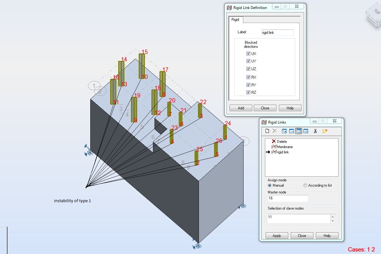
i have a rigid link with one master node and 4 slave nodes, i want to design another rigid link with a different master node and 4 slave nodes, where 2 of these slave nodes are also slave nodes from the 1st rigid link.as in the picture.
is there a problem regarding this or is just a graphical issue?
Can this be done selecting 2 nodes as master and the others as slaves? It seems like NOT to me.
Thanks
Message 16 of 18
07-27-2012
06:05 AM
- Mark as New
- Bookmark
- Subscribe
- Mute
- Subscribe to RSS Feed
- Permalink
- Report
07-27-2012
06:05 AM
Hello,
as it is written in Help: "A node can be defined as a slave node only in one rigid link."
If these 2 rigid links you mentioned are in reality one rigid body then I recommend defining it as one rigid link. I such case the master node of one or rigid links will change into slave node.
If these are in reality 2 separate different bodies then I recommend:
1/ or using finer mesh to use separete slave nodes for them
2/ or replacing rigid links with very rigid bars (in such case necessary to define material or loads and load to mass conversion in such way that mass of these bars will not be taken into account)
Regards,
Pawel Pulak
Technical Account Specialist
Message 17 of 18
07-27-2012
06:32 AM
- Mark as New
- Bookmark
- Subscribe
- Mute
- Subscribe to RSS Feed
- Permalink
- Report
07-27-2012
06:32 AM
I like the second option better,
so in this case Im defining a new material with high modulus of elasticity. Applying the new material to the bars that will connect the mass ( which will be substituted by force) to the bearing points. Is this correct?
Thanks
Message 18 of 18
07-27-2012
06:49 AM
- Mark as New
- Bookmark
- Subscribe
- Mute
- Subscribe to RSS Feed
- Permalink
- Report
07-27-2012
06:49 AM
It cab be even standard Young's modulus of steel (providing section properties are big). What is important is zero unit weight (density) of the new material - to avoid considering it in selfweight and vibrations.
Regards,
Pawel Pulak
Technical Account Specialist
Reply
Topic Options
- Subscribe to RSS Feed
- Mark Topic as New
- Mark Topic as Read
- Float this Topic for Current User
- Bookmark
- Subscribe
- Printer Friendly Page
