Community
- Forums Home
- >
- Robot Structural Analysis Products Community
- >
- Robot Structural Analysis Forum
- >
- Re: Problem with load applying in cladding
Robot Structural Analysis Forum
Welcome to Autodesk’s Robot Structural Analysis Forums. Share your knowledge, ask questions, and explore popular Robot Structural Analysis topics.
Turn on suggestions
Auto-suggest helps you quickly narrow down your search results by suggesting possible matches as you type.
Problem with load applying in cladding
5 REPLIES 5
SOLVED
Reply
Topic Options
- Subscribe to RSS Feed
- Mark Topic as New
- Mark Topic as Read
- Float this Topic for Current User
- Bookmark
- Subscribe
- Printer Friendly Page
Message 1 of 6
11-06-2012
04:40 AM
- Mark as New
- Bookmark
- Subscribe
- Mute
- Subscribe to RSS Feed
- Permalink
- Report
11-06-2012
04:40 AM
Hi,
I'm experiencing a problem when i try to apply a perpendicular load to A PART of a cladding. The program is generating a load according to global Z axis and i want to consider the cladding Z axis.
Please see pictures below:
1. Applying the Load:

2 - Final Result

The result should be : Load perpendicular to panel and with opposite sign!
I tryed with planar load 3p on contour and the result is the same.
Thanks in advance!
Filipe Ribeiro
Solved! Go to Solution.
Solved by Artur.Kosakowski. Go to Solution.
5 REPLIES 5
Message 2 of 6
11-06-2012
05:12 AM
- Mark as New
- Bookmark
- Subscribe
- Mute
- Subscribe to RSS Feed
- Permalink
- Report
11-06-2012
05:12 AM
Please check the attached picture. Mind to generate model first.
If you find your post answered press the Accept as Solution button please. This will help other users to find solutions much faster. Thank you.
Artur Kosakowski
Message 3 of 6
11-06-2012
06:38 AM
- Mark as New
- Bookmark
- Subscribe
- Mute
- Subscribe to RSS Feed
- Permalink
- Report
11-06-2012
06:38 AM
Hi Artur,
Thanks for the quick response, but i think you miss understood me.
This is what i want:

(this picture is edited in paint. I cant make the software generate a load like this)
And this is what i get (using uniform planar load on contour and with Planar load 3p on contour):

The loaded element its a cladding, not a bar! and i want to apply a load in part of it.

Thanks!
FR
EDIT: I'm reaching the conclusion that the calculations are right but the graphical representation is wrong. Is it true?
Message 4 of 6
11-06-2012
06:47 AM
- Mark as New
- Bookmark
- Subscribe
- Mute
- Subscribe to RSS Feed
- Permalink
- Report
11-06-2012
06:47 AM
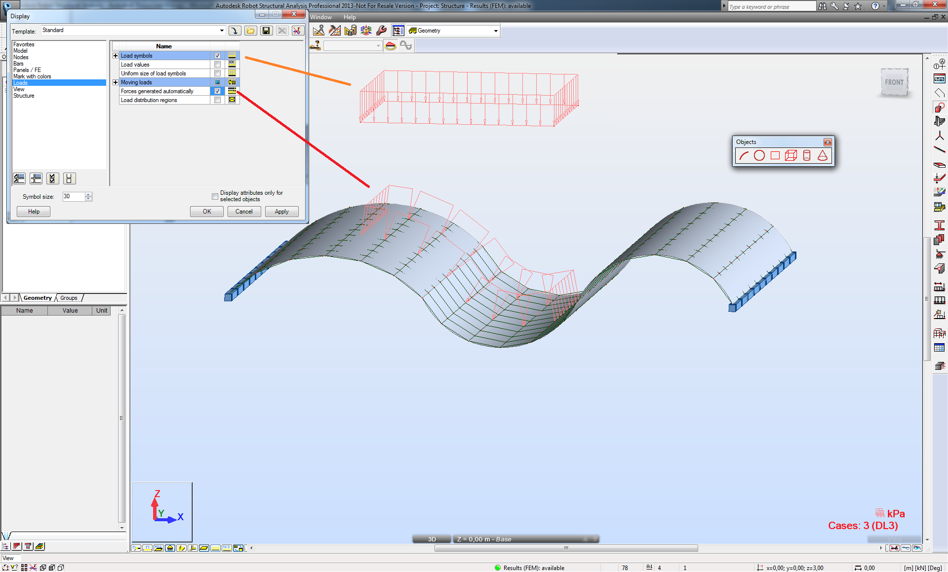
The display of the load definition is actually as you said but this is not the load as finally applied to the bars that 'support' the cladding. During the model generation this load is 'replaced' with load applied to the bars and which can be visible in the way I indicated on the picture (red frames). Such generated bar loads should no longer be vertical but inclined according to the local Z axis of the cladding. This is the reason the loads applied to bars are generated as vertical and horizontal ones (the equivalent loads will be parallel the local Z of the cladding).
If you find your post answered press the Accept as Solution button please. This will help other users to find solutions much faster. Thank you.
Artur Kosakowski
Message 5 of 6
11-06-2012
06:55 AM
- Mark as New
- Bookmark
- Subscribe
- Mute
- Subscribe to RSS Feed
- Permalink
- Report
11-06-2012
06:55 AM
Just a conclusion note:
I think the graphical representation should be perpendicular to cladding, otherwise it could lead to modeling errors.
Thanks!
Message 6 of 6
11-06-2012
07:09 AM
- Mark as New
- Bookmark
- Subscribe
- Mute
- Subscribe to RSS Feed
- Permalink
- Report
11-06-2012
07:09 AM
This load is a bit more versatile and therefore not that easy to be shown without switching to the 'model generated' one ![]()
Artur Kosakowski
Reply
Topic Options
- Subscribe to RSS Feed
- Mark Topic as New
- Mark Topic as Read
- Float this Topic for Current User
- Bookmark
- Subscribe
- Printer Friendly Page
