Community
- Forums Home
- >
- Robot Structural Analysis Products Community
- >
- Robot Structural Analysis Forum
- >
- Re: Modeling a Curved Roof
Robot Structural Analysis Forum
Welcome to Autodesk’s Robot Structural Analysis Forums. Share your knowledge, ask questions, and explore popular Robot Structural Analysis topics.
Turn on suggestions
Auto-suggest helps you quickly narrow down your search results by suggesting possible matches as you type.
Reply
Topic Options
- Subscribe to RSS Feed
- Mark Topic as New
- Mark Topic as Read
- Float this Topic for Current User
- Bookmark
- Subscribe
- Printer Friendly Page
Message 1 of 21
02-15-2013
11:51 AM
- Mark as New
- Bookmark
- Subscribe
- Mute
- Subscribe to RSS Feed
- Permalink
- Report
02-15-2013
11:51 AM
Hello,
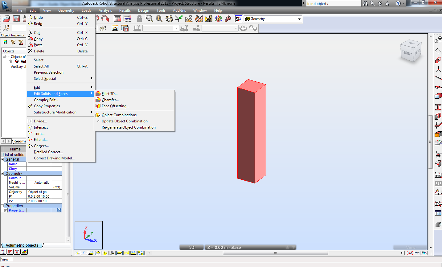
I'm trying to find a way to model a curved roof which would consist of several bended I-section beams. I would try Object Bending option however I cannot see such an option in the Edit menu (please see the attachment) eventhough the Solid Modeler is enabled.
I guess I can use the option Extrude Along Polyline however I don't prefer to bother with solids when there is a chance to use I-sections and analyse in Steel Design.
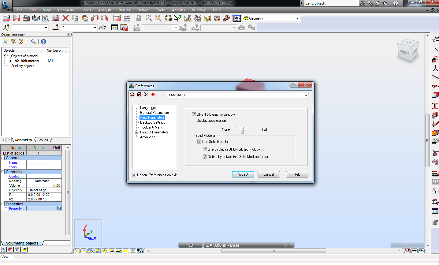
Can someone please tell me why the Solid Modeller options below Face offsetting as in the following link are missing for my version (I'm using RSA2013)? Also any ideas about how to model a curved roof under these circumstances are welcome.
P.S.: I tried both with Volumetric Structure Design and Shell Design Modules, no results.
http://docs.autodesk.com/RSA/2012/ENU/filesROBOT/GUID-6D12CC11-17B2-41B6-AD0D-2151F7D0935-418.htm
Thanks.
Solved! Go to Solution.
Solved by Artur.Kosakowski. Go to Solution.
20 REPLIES 20
Message 2 of 21
02-15-2013
11:20 PM
- Mark as New
- Bookmark
- Subscribe
- Mute
- Subscribe to RSS Feed
- Permalink
- Report
02-15-2013
11:20 PM
in the name of GOD .
hello luzer
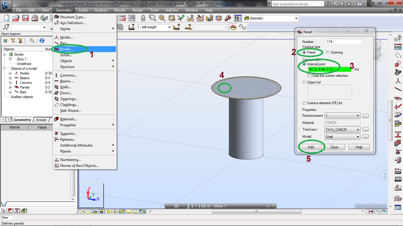
for modeling roof above your shape you should go to shell design in the first step and then follow numbers in attached image1 and then image 2.
if you can model a roof above your shape plaese prees button 'Accept as solution' below my answer.
Message 3 of 21
02-18-2013
12:09 AM
- Mark as New
- Bookmark
- Subscribe
- Mute
- Subscribe to RSS Feed
- Permalink
- Report
02-18-2013
12:09 AM
Could you attach the sketch of your roof?
In general any curve shape of a beam should be approximated by number of straight bars. You can use the steps shown below:

If you find your post answered press the Accept as Solution button please. This will help other users to find solutions much faster. Thank you.
Artur Kosakowski
Message 4 of 21
02-18-2013
03:01 AM
- Mark as New
- Bookmark
- Subscribe
- Mute
- Subscribe to RSS Feed
- Permalink
- Report
02-18-2013
03:01 AM
Sorry I don't have any sketches of the model but the section view would look like your attached example. However if I model the roof that way, would the bending strenght of the whole beam overestimated because of the lenght of the each segment? As far as I know, Robot would analyse each segment by itself. For example if the whole beam is 30m in length and is divided into 10 parts, the bending moment would be applied onto 3m segments and bending strength would be found that way which would not reflect the exact reality. The only way to examine this kind of a model would be looking at the displacements of the nodes.
Your comments would be appriciated.
Message 5 of 21
02-18-2013
03:12 AM
- Mark as New
- Bookmark
- Subscribe
- Mute
- Subscribe to RSS Feed
- Permalink
- Report
02-18-2013
03:12 AM
You can create a superbar (new member) for the steel design procedure that includes all the straight segments of the arch.
If you find your post answered press the Accept as Solution button please. This will help other users to find solutions much faster. Thank you.
Artur Kosakowski
Message 6 of 21
02-18-2013
05:21 AM
- Mark as New
- Bookmark
- Subscribe
- Mute
- Subscribe to RSS Feed
- Permalink
- Report
02-18-2013
05:21 AM
That will satisfy my question, thanks a lot. For those who are looking for "superbar",
http://208.74.205.69/t5/Autodesk-Robot-Structural/Probl%C3%A8me-de-mod%C3%A9lisation-steel-design/td... (message 9, the attachment)
Message 7 of 21
02-19-2013
12:18 PM
- Mark as New
- Bookmark
- Subscribe
- Mute
- Subscribe to RSS Feed
- Permalink
- Report
02-19-2013
12:18 PM
And do you have any ideas about why Object Bending option does not appear on the Edit menu?
Message 8 of 21
02-20-2013
12:06 AM
- Mark as New
- Bookmark
- Subscribe
- Mute
- Subscribe to RSS Feed
- Permalink
- Report
02-20-2013
12:06 AM
I'm sorry but I'm not sure if I understand you correctly. I'm not aware of any 'bending option' for bar elements.
Artur Kosakowski
Message 9 of 21
02-21-2013
04:21 AM
- Mark as New
- Bookmark
- Subscribe
- Mute
- Subscribe to RSS Feed
- Permalink
- Report
02-21-2013
04:21 AM
"The current version of Robot lets you perform the following operations on objects using Solid Modeler:
- Fillet 3D
- Chamfer
- Object combinations
- Face skinning
- Face offsetting
- Object bending
- Object stretching
- Object twisting
- Object warping"
The quote is from the following link,
http://docs.autodesk.com/RSA/2012/ENU/filesROBOT/GUID-6D12CC11-17B2-41B6-AD0D-2151F7D0935-418.htm
Message 10 of 21
02-21-2013
04:43 AM
- Mark as New
- Bookmark
- Subscribe
- Mute
- Subscribe to RSS Feed
- Permalink
- Report
02-21-2013
04:43 AM
This doesn't apply to linear elements (bars). The key word is solid ![]()
Artur Kosakowski
Message 11 of 21
02-21-2013
05:50 AM
- Mark as New
- Bookmark
- Subscribe
- Mute
- Subscribe to RSS Feed
- Permalink
- Report
02-21-2013
05:50 AM
Yes but still the command doesn't show up even in the volumetric structure design module eventhough an object is sellected as you can see in the attachment of my first message. I don't use the solid modeller too often but just curious.
Message 12 of 21
02-21-2013
06:00 AM
- Mark as New
- Bookmark
- Subscribe
- Mute
- Subscribe to RSS Feed
- Permalink
- Report
02-21-2013
06:00 AM
Some of these options are available only for Robot versions manufactured by Robobat prior to its acquisition by Autodesk. They depend on the version of ACIS geometrical kernel.
Artur Kosakowski
Message 13 of 21
02-21-2013
07:37 AM
- Mark as New
- Bookmark
- Subscribe
- Mute
- Subscribe to RSS Feed
- Permalink
- Report
Message 15 of 21
09-12-2013
04:14 AM
- Mark as New
- Bookmark
- Subscribe
- Mute
- Subscribe to RSS Feed
- Permalink
- Report

Message 16 of 21
07-01-2014
05:23 PM
- Mark as New
- Bookmark
- Subscribe
- Mute
- Subscribe to RSS Feed
- Permalink
- Report
07-01-2014
05:23 PM
So I am analysing a penstock reducer, which is basically a pipe that has a square openeing 2mx2m at one side and a circle 1.6m diameter in the other side and this pipe is 4m long.
since the face skinning (lofting) is not available in RSA now, does anyone know how to model that with refined FE size?
this pipe is burried with soil load on top in one load case and water pressure from inside as another load case.
Thanks.
Message 17 of 21
07-01-2014
11:34 PM
- Mark as New
- Bookmark
- Subscribe
- Mute
- Subscribe to RSS Feed
- Permalink
- Report
07-01-2014
11:34 PM
Are you looking for something like that ?:
http://forums.autodesk.com/t5/Robot-Structural-Analysis/Shell-problem-opening/m-p/3786094#M10932
http://forums.autodesk.com/t5/Robot-Structural-Analysis/Object-Combinations/m-p/4320369#M15069

Rafal Gaweda
http://forums.autodesk.com/t5/Robot-Structural-Analysis/Shell-problem-opening/m-p/3786094#M10932
http://forums.autodesk.com/t5/Robot-Structural-Analysis/Object-Combinations/m-p/4320369#M15069
Rafal Gaweda
Message 18 of 21
07-02-2014
08:14 AM
- Mark as New
- Bookmark
- Subscribe
- Mute
- Subscribe to RSS Feed
- Permalink
- Report

Message 19 of 21
07-03-2014
12:27 AM
- Mark as New
- Bookmark
- Subscribe
- Mute
- Subscribe to RSS Feed
- Permalink
- Report
Message 20 of 21
07-03-2014
09:33 AM
- Mark as New
- Bookmark
- Subscribe
- Mute
- Subscribe to RSS Feed
- Permalink
- Report
Reply
Topic Options
- Subscribe to RSS Feed
- Mark Topic as New
- Mark Topic as Read
- Float this Topic for Current User
- Bookmark
- Subscribe
- Printer Friendly Page
Forums Links
Can't find what you're looking for? Ask the community or share your knowledge.
Post to forums
