Community
- Forums Home
- >
- Robot Structural Analysis Products Community
- >
- Robot Structural Analysis Forum
- >
- Re: Lateral buckling verification in several sections
Robot Structural Analysis Forum
Welcome to Autodesk’s Robot Structural Analysis Forums. Share your knowledge, ask questions, and explore popular Robot Structural Analysis topics.
Turn on suggestions
Auto-suggest helps you quickly narrow down your search results by suggesting possible matches as you type.
Lateral buckling verification in several sections
20 REPLIES 20
SOLVED
Reply
Topic Options
- Subscribe to RSS Feed
- Mark Topic as New
- Mark Topic as Read
- Float this Topic for Current User
- Bookmark
- Subscribe
- Printer Friendly Page
Message 1 of 21
Anonymous
2617 Views, 20 Replies
02-01-2013
08:03 AM
- Mark as New
- Bookmark
- Subscribe
- Mute
- Subscribe to RSS Feed
- Permalink
- Report
02-01-2013
08:03 AM
Hi
I'm trying to calculate an old steel girder bridge in 3D using RSA and I came across a problem regarding the verifications for lateral buckling.
Because it’s an old bridge, all sections are riveted sections formed with plates and angles. These sections are not available in RSA, so I create them myself and created a user database.
There is one particular beam who is heavily loaded, and it has several sections all along. The areas of the sections in middle span are grater than those close to the supports.
The problem is that the change in the sections does not correspond to the distance between supports (5 supports in total), i.e. in one span I have 2 or 3 different sections.
So I’m forced to create several bars in one span, for example, in a 3.9 m span I have 3 sections, so I create 3 bars of 1.3m each, and create the supports only at the beginning of the first bar and at the ending of the last.
When I do the verification of the beam for lateral buckling, RSA takes 1.3 m as the buckling length for each bar, and I want it to take 3.9 m instead !
Now, I know that there is a way around this, I only have to specify Lcr=3lo in my example. But the problem is that when I go to Detailed Analysis to specify stiffeners and all that, RSA only takes one bar of 1.3 m with supports at the beginning and the end of this bar, which is not true.
Is there a way to take all the 3 bars and make a detailed analysis and lateral buckling verification?
Solved! Go to Solution.
Solved by Artur.Kosakowski. Go to Solution.
20 REPLIES 20
Message 2 of 21
02-01-2013
08:09 AM
- Mark as New
- Bookmark
- Subscribe
- Mute
- Subscribe to RSS Feed
- Permalink
- Report
02-01-2013
08:09 AM
Try the following approach:
1. Create a new superbar (member) typing the numbers of 'several bars' you refer to in the list field
2. Define a positions of LTB bracings for such created member
If you find your post answered press the Accept as Solution button please. This will help other users to find solutions much faster. Thank you.
Artur Kosakowski
Message 3 of 21
02-04-2013
11:57 PM
- Mark as New
- Bookmark
- Subscribe
- Mute
- Subscribe to RSS Feed
- Permalink
- Report
Message 4 of 21
Anonymous
in reply to:
Anonymous
02-06-2013
07:31 AM
- Mark as New
- Bookmark
- Subscribe
- Mute
- Subscribe to RSS Feed
- Permalink
- Report
02-06-2013
07:31 AM
Hi,
kind of having the same problem.
Can you please show somehow: 1. Create a new superbar (member) typing the numbers of 'several bars' you refer to in the list field.
Thanks
Message 5 of 21
02-06-2013
08:01 AM
- Mark as New
- Bookmark
- Subscribe
- Mute
- Subscribe to RSS Feed
- Permalink
- Report
02-06-2013
08:01 AM
Please check http://forums.autodesk.com/t5/Autodesk-Robot-Structural/Probl%C3%A8me-de-mod%C3%A9lisation-steel-des... (message 9).
Out of curiosity - haven't you discussed this in http://forums.autodesk.com/t5/Autodesk-Robot-Structural/member-design-upper-chord/m-p/3765119 ![]()
Artur Kosakowski
Message 6 of 21
02-06-2013
08:10 AM
- Mark as New
- Bookmark
- Subscribe
- Mute
- Subscribe to RSS Feed
- Permalink
- Report
02-06-2013
08:10 AM
![]()
Yes, I did discuss buckling,
this was regarding a bar with different sections, so in this case we use group- group the bars with different sections in a new superbar, and analyze it. Is it correct?
Thanks
Message 7 of 21
02-06-2013
08:15 AM
- Mark as New
- Bookmark
- Subscribe
- Mute
- Subscribe to RSS Feed
- Permalink
- Report
02-06-2013
08:15 AM
You should look at the element you want to design as it was the real one. You determine where it actually starts (is supported) and where it ends (is supported again). If in the model this element is divided into smaller parts (regardless of their sections)you create a super bar.
Artur Kosakowski
Message 8 of 21
04-10-2014
01:09 AM
- Mark as New
- Bookmark
- Subscribe
- Mute
- Subscribe to RSS Feed
- Permalink
- Report
04-10-2014
01:09 AM
Hello,
i have one question, didn't want to make onother post.
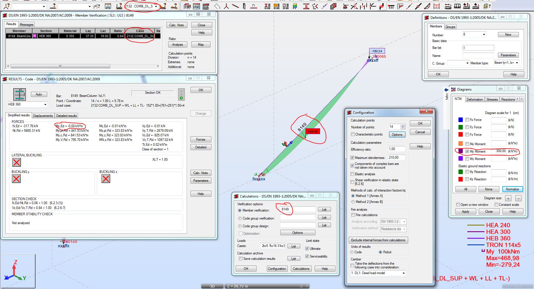
If i have beam let's say HEB360, and when i do verification of this beam, program says to me, that "For bar ... the program has not performed lateral buckling verification. And so on..."
Can you tell me why? See files atatched. Its from a big structure and design ratio is not important.
Thank you.
Message 9 of 21
04-10-2014
01:49 AM
- Mark as New
- Bookmark
- Subscribe
- Mute
- Subscribe to RSS Feed
- Permalink
- Report
04-10-2014
01:49 AM
Robot displays the verification result from the point where the ratio is the larges x=1.0L -> 0.84 where there is no My bending (therefore no LTB check is done). If you force the verification in the pint you indicated you can see that the obtained ration is smaller (0.76) with LTB verification (My is not zero).
If you find your post answered press the Accept as Solution button please. This will help other users to find solutions much faster. Thank you.
Artur Kosakowski
Message 10 of 21
04-10-2014
02:38 AM
- Mark as New
- Bookmark
- Subscribe
- Mute
- Subscribe to RSS Feed
- Permalink
- Report
Message 11 of 21
04-10-2014
03:01 AM
- Mark as New
- Bookmark
- Subscribe
- Mute
- Subscribe to RSS Feed
- Permalink
- Report
04-10-2014
03:01 AM
For the situation we you described I can't see any issue.
Artur Kosakowski
Message 12 of 21
01-01-2015
08:22 PM
- Mark as New
- Bookmark
- Subscribe
- Mute
- Subscribe to RSS Feed
- Permalink
- Report
01-01-2015
08:22 PM
i don't know what problem on the message related to bukcling, although I checked all member in "Steel Member type " icon.
Message 13 of 21
01-05-2015
05:08 AM
- Mark as New
- Bookmark
- Subscribe
- Mute
- Subscribe to RSS Feed
- Permalink
- Report
01-05-2015
05:08 AM
Mind that in Robot there are two families of angles. In most of the cases you should use the one with properties calculated for the principal axes rather than the ones that are parallel to the legs.

If you find your post answered press the Accept as Solution button please. This will help other users to find solutions much faster. Thank you.
Artur Kosakowski
Message 14 of 21
01-05-2015
04:24 PM
- Mark as New
- Bookmark
- Subscribe
- Mute
- Subscribe to RSS Feed
- Permalink
- Report
Message 15 of 21
01-07-2015
05:47 PM
- Mark as New
- Bookmark
- Subscribe
- Mute
- Subscribe to RSS Feed
- Permalink
- Report
Message 16 of 21
01-08-2015
12:12 AM
- Mark as New
- Bookmark
- Subscribe
- Mute
- Subscribe to RSS Feed
- Permalink
- Report
01-08-2015
12:12 AM
Two possible reasons:
1. Section type is such that the code has got no provisions for LTB check e.g. an angle; a pipe etc.
2. The verification is done at the location where bending moment is equal 0 e.g. at the support of a simply supported beam
If you find your post answered press the Accept as Solution button please. This will help other users to find solutions much faster. Thank you.
Artur Kosakowski
Message 17 of 21
01-08-2015
05:42 PM
- Mark as New
- Bookmark
- Subscribe
- Mute
- Subscribe to RSS Feed
- Permalink
- Report
Message 18 of 21
01-29-2015
06:37 PM
- Mark as New
- Bookmark
- Subscribe
- Mute
- Subscribe to RSS Feed
- Permalink
- Report
01-29-2015
06:37 PM
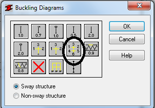
i have probleme that i do not know how to solve it. i design red column it appeares this message and ratio is too hieght after i choose these columns (bar definition) as firgure bellow (black circle).
Message 19 of 21
01-29-2015
11:57 PM
- Mark as New
- Bookmark
- Subscribe
- Mute
- Subscribe to RSS Feed
- Permalink
- Report
01-29-2015
11:57 PM
Try to increase their sizes. What are the buckling coefficients for them (you can find them in the calculation notes)?
If you find your post answered press the Accept as Solution button please. This will help other users to find solutions much faster. Thank you.
Artur Kosakowski
Message 20 of 21
01-30-2015
05:44 PM
- Mark as New
- Bookmark
- Subscribe
- Mute
- Subscribe to RSS Feed
- Permalink
- Report
01-30-2015
05:44 PM
ky = 1.06 kz = 1.6. But when i take values (design stress and allowable stress) from calculation note into the formular, the result not true as value in calculation note.
Anywhere if i use this icon ky=kz=1 and result ok!.
Is it right if i use this icon? Cause my column is 9m and unbrace length locates 3m.
Reply
Topic Options
- Subscribe to RSS Feed
- Mark Topic as New
- Mark Topic as Read
- Float this Topic for Current User
- Bookmark
- Subscribe
- Printer Friendly Page
