Community
- Forums Home
- >
- Robot Structural Analysis Products Community
- >
- Robot Structural Analysis Forum
- >
- How to interpret moment on panel map result??
Robot Structural Analysis Forum
Welcome to Autodesk’s Robot Structural Analysis Forums. Share your knowledge, ask questions, and explore popular Robot Structural Analysis topics.
Turn on suggestions
Auto-suggest helps you quickly narrow down your search results by suggesting possible matches as you type.
How to interpret moment on panel map result??
6 REPLIES 6
SOLVED
Reply
Topic Options
- Subscribe to RSS Feed
- Mark Topic as New
- Mark Topic as Read
- Float this Topic for Current User
- Bookmark
- Subscribe
- Printer Friendly Page
Message 1 of 7
Anonymous
2832 Views, 6 Replies
08-20-2014
08:25 AM
- Mark as New
- Bookmark
- Subscribe
- Mute
- Subscribe to RSS Feed
- Permalink
- Report
08-20-2014
08:25 AM
Hi!
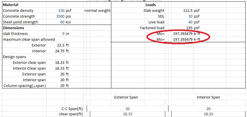
Please help me interpreting the moment results on the panel (slab).
I've attached two images: one with hand calculation of getting the maximum bending moment on the slab (DDM) and one with my robot model.
I simply don't know how to interpret the map or cut result of slab.
I've done lot of steel design using robot, but not much on panel design. However, I believe my model is correct.
I am currently trying to prove my office that robot can be used to design slab, but I failed to convince them because I didn't know how to interpret the result.
I believe the maximum bending moment must be at least similar to the one by hand calculation.
Please help me. Thank you!
Solved! Go to Solution.
Solved by Artur.Kosakowski. Go to Solution.
6 REPLIES 6
Message 2 of 7
08-21-2014
12:03 AM
- Mark as New
- Bookmark
- Subscribe
- Mute
- Subscribe to RSS Feed
- Permalink
- Report
08-21-2014
12:03 AM
Pease check:
http://forums.autodesk.com/t5/Robot-Structural-Analysis/strip-method/m-p/4923878
http://forums.autodesk.com/t5/Robot-Structural-Ana
http://forums.autodesk.com/t5/Robot-Structural-Ana
If you find your post answered press the Accept as Solution button please. This will help other users to find solutions much faster. Thank you.
Artur Kosakowski
Message 4 of 7
04-11-2018
03:54 AM
- Mark as New
- Bookmark
- Subscribe
- Mute
- Subscribe to RSS Feed
- Permalink
- Report
Message 5 of 7
04-16-2018
05:00 AM
- Mark as New
- Bookmark
- Subscribe
- Mute
- Subscribe to RSS Feed
- Permalink
- Report
04-16-2018
05:00 AM
No, the right topic. I wanted to know the answer to this post. However, have not quite found it in any of the attached 3 links.
Message 6 of 7
04-16-2018
05:10 AM
- Mark as New
- Bookmark
- Subscribe
- Mute
- Subscribe to RSS Feed
- Permalink
- Report
Message 7 of 7
04-16-2018
06:06 AM
- Mark as New
- Bookmark
- Subscribe
- Mute
- Subscribe to RSS Feed
- Permalink
- Report
Reply
Topic Options
- Subscribe to RSS Feed
- Mark Topic as New
- Mark Topic as Read
- Float this Topic for Current User
- Bookmark
- Subscribe
- Printer Friendly Page
