Community
Inventor Forum
Welcome to Autodesk’s Inventor Forums. Share your knowledge, ask questions, and explore popular Inventor topics.
Turn on suggestions
Auto-suggest helps you quickly narrow down your search results by suggesting possible matches as you type.
Reply
Topic Options
- Subscribe to RSS Feed
- Mark Topic as New
- Mark Topic as Read
- Float this Topic for Current User
- Bookmark
- Subscribe
- Printer Friendly Page
Message 1 of 16
04-04-2008
07:25 AM
- Mark as New
- Bookmark
- Subscribe
- Mute
- Subscribe to RSS Feed
- Permalink
- Report
04-04-2008
07:25 AM
Thread. xls - Incorrect Tap drill callouts?
Has anyone else noticed that the tap drills for the NPT hole callouts are not consistent with any conventional standard?
Am I just not reading the table right? Or am I referencing some old standard tap drill table?
1/4-18 npt calls out a .422 in tap drill
I am finding that .4375 in is the correct drill size
3/8-18 npt calls out a .5468 in
I am finding that .578 in is the correct drill size
These are just two for example. Anyone else have any comments on this?
Thanks,
Jeremy
15 REPLIES 15
Message 2 of 16
04-04-2008
07:56 AM
- Mark as New
- Bookmark
- Subscribe
- Mute
- Subscribe to RSS Feed
- Permalink
- Report
04-04-2008
07:56 AM
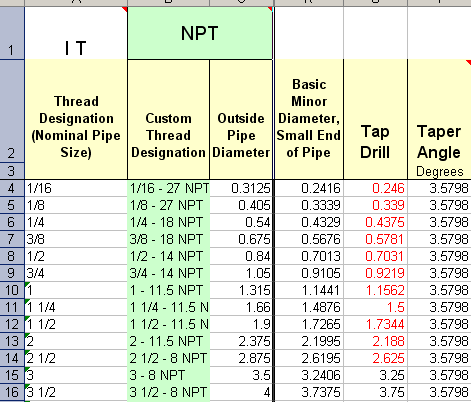
In R2008, here is what I have changed my table to. The ones shown in red were changed to met the values shown in any tap-drill chart that you can pick up.
I don't have R2009 in front of me, so I can't check that. I was hoping that got corrected.

I don't have R2009 in front of me, so I can't check that. I was hoping that got corrected.
Message 3 of 16
04-04-2008
08:08 AM
- Mark as New
- Bookmark
- Subscribe
- Mute
- Subscribe to RSS Feed
- Permalink
- Report
04-04-2008
08:08 AM
NPT holes are typically tapered.
Autodesk seems to put the minimum size.
Just change the excel table to meet your companies needs.
-------------------------------------------------------------------------------------------
Inventor 2023 - Dell Precision 5570
Did you find this reply helpful ? If so please use the Accept Solution button below.
Maybe buy me a beer through Venmo @mcgyvr1269
Message 4 of 16
04-04-2008
08:10 AM
- Mark as New
- Bookmark
- Subscribe
- Mute
- Subscribe to RSS Feed
- Permalink
- Report
04-04-2008
08:10 AM
Yes. this what we ended up doing. But if you only update the tap drill diameter, the feature doesn't display properly on the drawing or model. It shows the threads to be really short. You have to change the other parameters to match the change in tap drill diameter. We did not do this, of course. that would be a huge waste of time. So we just changed the taper angle to 2 degrees. Just so that drawing view displays something close to reality.
But, where did these values come from? I am new to inventor. Has this problem been around for several releases, or was it just this one?
But, where did these values come from? I am new to inventor. Has this problem been around for several releases, or was it just this one?
Message 5 of 16
04-04-2008
08:56 AM
- Mark as New
- Bookmark
- Subscribe
- Mute
- Subscribe to RSS Feed
- Permalink
- Report
04-04-2008
08:56 AM
The latest "Machinists Handbook 27th edition" call for a minor dia of .438
without reamer and .422 with reamer for 1/4" NPT.
Page 1868 table 8
--
Dell 670 dual Xeon - 3.2
3gb memory, SCSI320-15k
XP-Pro, sp2
Quadro FX3400: Driver: 169.61 Direct3D
IV2008-pro sp2,
SpacePilot Rel V: 3.5.6 Dvr V: 6.5.5 Firmware 3.12
wrote in message news:5895412@discussion.autodesk.com...
Yes. this what we ended up doing. But if you only update the tap drill
diameter, the feature doesn't display properly on the drawing or model. It
shows the threads to be really short. You have to change the other
parameters to match the change in tap drill diameter. We did not do this, of
course. that would be a huge waste of time. So we just changed the taper
angle to 2 degrees. Just so that drawing view displays something close to
reality.
But, where did these values come from? I am new to inventor. Has this
problem been around for several releases, or was it just this one?
without reamer and .422 with reamer for 1/4" NPT.
Page 1868 table 8
--
Dell 670 dual Xeon - 3.2
3gb memory, SCSI320-15k
XP-Pro, sp2
Quadro FX3400: Driver: 169.61 Direct3D
IV2008-pro sp2,
SpacePilot Rel V: 3.5.6 Dvr V: 6.5.5 Firmware 3.12
Yes. this what we ended up doing. But if you only update the tap drill
diameter, the feature doesn't display properly on the drawing or model. It
shows the threads to be really short. You have to change the other
parameters to match the change in tap drill diameter. We did not do this, of
course. that would be a huge waste of time. So we just changed the taper
angle to 2 degrees. Just so that drawing view displays something close to
reality.
But, where did these values come from? I am new to inventor. Has this
problem been around for several releases, or was it just this one?
Message 6 of 16
04-04-2008
09:07 AM
- Mark as New
- Bookmark
- Subscribe
- Mute
- Subscribe to RSS Feed
- Permalink
- Report
04-04-2008
09:07 AM
Yes. I see how that value can be seen as correct. But what about the others. Am I just overlooking something?
I don't have 27th. I have the 26th edition. It has the same table
I don't have 27th. I have the 26th edition. It has the same table
Message 7 of 16
04-04-2008
10:51 AM
- Mark as New
- Bookmark
- Subscribe
- Mute
- Subscribe to RSS Feed
- Permalink
- Report
04-04-2008
10:51 AM
You might also checkout this web page (watch for word wrap):
http://www.precisiontwistdrill.com/techhelp/help_pages/tap_projection_minor_diameters.asp
It's not definitive and many companies have slightly differing drill size suggestions. The biggest factor is the material you're drilling and tapping: softer steel, smaller hole; harder steel, bigger hole. Plus, there's the whole to taper ream or not to taper ream question.
BTW, I hate pipe threads - I almost wish they were illegal But I think companies still make products with pipe threads because the pipe fittings are cheaper than SAE fittings.
KState92
Inventor Professional 2020
AutoCAD Mechanical 2022.0.1
Windows 10 Pro 64 bit - 1903
Core i7-8700 32 GB Ram
Quadro P2000
Inventor Professional 2020
AutoCAD Mechanical 2022.0.1
Windows 10 Pro 64 bit - 1903
Core i7-8700 32 GB Ram
Quadro P2000
Message 8 of 16
04-05-2008
10:09 AM
- Mark as New
- Bookmark
- Subscribe
- Mute
- Subscribe to RSS Feed
- Permalink
- Report
04-05-2008
10:09 AM
NPT would be cheaper than JIC or ORB, only involves the drill and thread, no
machined face to seat/seal against.
--
Dell Precision 690
Dual Quad Core E5320 @ 1.86GHz
4Gb DDR SDRam - 667 Mhz, ECC
SAS 146Gb - 15k rpm
Quadro FX3500 256Mb - Driver: 169.61 Bios: 5.71.22.55.08
XP Pro Sp2 - AIP 2008sp2 - D3D
Space Explorer USB 3.5.6
wrote in message news:5895700@discussion.autodesk.com...
You might also checkout this web page (watch for word wrap):
http://www.precisiontwistdrill.com/techhelp/help_pages/tap_projection_minor_diameters.asp
It's not definitive and many companies have slightly differing drill size
suggestions. The biggest factor is the material you're drilling and
tapping: softer steel, smaller hole; harder steel, bigger hole. Plus,
there's the whole to taper ream or not to taper ream question.
BTW, I hate pipe threads - I almost wish they were illegal But I think
companies still make products with pipe threads because the pipe fittings
are cheaper than SAE fittings.
machined face to seat/seal against.
--
Dell Precision 690
Dual Quad Core E5320 @ 1.86GHz
4Gb DDR SDRam - 667 Mhz, ECC
SAS 146Gb - 15k rpm
Quadro FX3500 256Mb - Driver: 169.61 Bios: 5.71.22.55.08
XP Pro Sp2 - AIP 2008sp2 - D3D
Space Explorer USB 3.5.6
You might also checkout this web page (watch for word wrap):
http://www.precisiontwistdrill.com/techhelp/help_pages/tap_projection_minor_diameters.asp
It's not definitive and many companies have slightly differing drill size
suggestions. The biggest factor is the material you're drilling and
tapping: softer steel, smaller hole; harder steel, bigger hole. Plus,
there's the whole to taper ream or not to taper ream question.
BTW, I hate pipe threads - I almost wish they were illegal But I think
companies still make products with pipe threads because the pipe fittings
are cheaper than SAE fittings.
Message 9 of 16
06-22-2011
05:24 AM
- Mark as New
- Bookmark
- Subscribe
- Mute
- Subscribe to RSS Feed
- Permalink
- Report
06-22-2011
05:24 AM
BTW, there is another problem with threads:
Let take ISO metric standard.
We have one assembly where M20x1,5 thread goes through couple of parts (manufactured at assembly itself)
Both parts do already have plain 18,5mm dia holes (as supposed).
Inventor (up to release 2012) refuses to build thread in the assembly (the feature didn't change the number of faces...) unless diameter be <=18.376mm (even so Tap drill diameter is 18,5mm).
Isn't that something that should be improved?
MaxU77,
AI2011 Certified Associate
(Soft: PDSU2012, VP2012&VP2013)
AI2011 Certified Associate
(Soft: PDSU2012, VP2012&VP2013)
Message 10 of 16
04-03-2014
07:07 PM
- Mark as New
- Bookmark
- Subscribe
- Mute
- Subscribe to RSS Feed
- Permalink
- Report
04-03-2014
07:07 PM
We use feature recognition software here, and when inventor refuses to model something correctly, we are forced to hand-program (when we catch it) the feature for our CNC's. Pipe threads are typically used here for grease zerks and some other lubrication features. This is a very frustrating flaw in Inventor. Even modifying the thread.xls file is difficult; The parameter(s) that drive the feature are absolutely ludicrous.
After changing values in the thread table, one column at a time, and re-starting inventor repeatedly (to purge the cached thread table), I have finally identified the parameter that needs changed when you correct the tap drill diameter. If you change this value by the same amount as the tap-drill change, it appears to properly generate the feature in the model. I have only done the 1/8 NPT so far (as that is the one I need on this model), but I'm sure this will help those others having this same issue.
I used a slightly tweaked "wrench makup diameter" then described above so the bottom of the taper is nearly the same diameter as the tap drill.
why would "Wrench makeup" have anything to do with modeling this feature. Do I have some ignorance that's preventing me from seeing the correlation? If this is the case, please, someone fill me in.
It's unfortunate that Most Machine Designers are not computer programmers/and computer programmers are not machine designers. This is fairly evident in inventor.
Message 12 of 16
03-16-2017
09:44 AM
- Mark as New
- Bookmark
- Subscribe
- Mute
- Subscribe to RSS Feed
- Permalink
- Report
03-16-2017
09:44 AM
By default: C:\Users\Public\Documents\Autodesk\Inventor <version>\Design Data\XLS\en-US
Mark Lancaster
& Autodesk Services MarketPlace Provider
Autodesk Inventor Certified Professional & not an Autodesk Employee
Likes is much appreciated if the information I have shared is helpful to you and/or others
Did this resolve your issue? Please accept it "As a Solution" so others may benefit from it.
Message 13 of 16
03-16-2017
09:45 AM
- Mark as New
- Bookmark
- Subscribe
- Mute
- Subscribe to RSS Feed
- Permalink
- Report
03-16-2017
09:45 AM
@cadcamm99 wrote:
where is the table located?
@cadcamm99 Its located in the XLS folder where your design data/style library stuff is..
-------------------------------------------------------------------------------------------
Inventor 2023 - Dell Precision 5570
Did you find this reply helpful ? If so please use the Accept Solution button below.
Maybe buy me a beer through Venmo @mcgyvr1269
Message 14 of 16
03-16-2017
09:46 AM
- Mark as New
- Bookmark
- Subscribe
- Mute
- Subscribe to RSS Feed
- Permalink
- Report
03-16-2017
09:46 AM
@mcgyvr Too slow today... ![]()
Mark Lancaster
& Autodesk Services MarketPlace Provider
Autodesk Inventor Certified Professional & not an Autodesk Employee
Likes is much appreciated if the information I have shared is helpful to you and/or others
Did this resolve your issue? Please accept it "As a Solution" so others may benefit from it.
Message 15 of 16
03-16-2017
09:55 AM
- Mark as New
- Bookmark
- Subscribe
- Mute
- Subscribe to RSS Feed
- Permalink
- Report
03-16-2017
09:55 AM
@Mark.Lancaster wrote:
@mcgyvr Too slow today...
But thats not where my thread file is.. and many others I'm sure.. ![]()
Lets be like power rangers and combine to be one super power..
Mark..
By default: C:\Users\Public\Documents\Autodesk\Inventor <version>\Design Data\XLS\en-US
+ Me
Its located in the XLS folder where your design data/style library stuff is..
+ A little extra
That can be found by looking at your project file settings..
= Super Answer... ![]()
-------------------------------------------------------------------------------------------
Inventor 2023 - Dell Precision 5570
Did you find this reply helpful ? If so please use the Accept Solution button below.
Maybe buy me a beer through Venmo @mcgyvr1269
Message 16 of 16
03-16-2017
01:19 PM
- Mark as New
- Bookmark
- Subscribe
- Mute
- Subscribe to RSS Feed
- Permalink
- Report
03-16-2017
01:19 PM
The thread taper however still wants to go to the .422 dim making the thread length small. According to Inventor the taper length should be .395. But after changing the drill size to .4375, the length is smaller even though Inventor shows it at .395.
Reply
Topic Options
- Subscribe to RSS Feed
- Mark Topic as New
- Mark Topic as Read
- Float this Topic for Current User
- Bookmark
- Subscribe
- Printer Friendly Page
