Community
Inventor Forum
Welcome to Autodesk’s Inventor Forums. Share your knowledge, ask questions, and explore popular Inventor topics.
Turn on suggestions
Auto-suggest helps you quickly narrow down your search results by suggesting possible matches as you type.
Reply
Topic Options
- Subscribe to RSS Feed
- Mark Topic as New
- Mark Topic as Read
- Float this Topic for Current User
- Bookmark
- Subscribe
- Printer Friendly Page
Message 1 of 17
Anonymous
3296 Views, 16 Replies
01-09-2013
07:17 PM
- Mark as New
- Bookmark
- Subscribe
- Mute
- Subscribe to RSS Feed
- Permalink
- Report
01-09-2013
07:17 PM
Trying to model a track but i have it in more of a triangular orientation then an ovel like this sample picture. Any advice on how to pattern the tread and inner lug around any shape i desire? I have tried making an extrusion on one of the flat faces and then patterning it around but it keeps the lug in the same orientation and does not follow the contour nicely. Any advice for me
?

Solved! Go to Solution.
Solved by VdVeek. Go to Solution.
16 REPLIES 16
Message 2 of 17
Anonymous
in reply to:
Anonymous
01-09-2013
11:36 PM
- Mark as New
- Bookmark
- Subscribe
- Mute
- Subscribe to RSS Feed
- Permalink
- Report
01-09-2013
11:36 PM
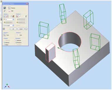
You can do rectangular pattern in part enviroment along choosen curve, and set orientation to direction1. This should work.
I hope that's what you're looking for.
Greg
Message 3 of 17
01-10-2013
04:42 AM
- Mark as New
- Bookmark
- Subscribe
- Mute
- Subscribe to RSS Feed
- Permalink
- Report
01-10-2013
04:42 AM
@Anonymous wrote:Trying to model a track but i have it in more of a triangular orientation . Any advice for me?
See this document pg 16
http://home.pct.edu/~jmather/SkillsUSA%20University.pdf
-----------------------------------------------------------------------------------------
Autodesk Inventor 2019 Certified Professional
Autodesk AutoCAD 2013 Certified Professional
Certified SolidWorks Professional
Message 4 of 17
01-10-2013
06:19 PM
- Mark as New
- Bookmark
- Subscribe
- Mute
- Subscribe to RSS Feed
- Permalink
- Report
Message 5 of 17
01-10-2013
06:55 PM
- Mark as New
- Bookmark
- Subscribe
- Mute
- Subscribe to RSS Feed
- Permalink
- Report
01-10-2013
06:55 PM
Attach your ipt file here.
-----------------------------------------------------------------------------------------
Autodesk Inventor 2019 Certified Professional
Autodesk AutoCAD 2013 Certified Professional
Certified SolidWorks Professional
Message 7 of 17
01-11-2013
04:47 AM
- Mark as New
- Bookmark
- Subscribe
- Mute
- Subscribe to RSS Feed
- Permalink
- Report
01-11-2013
04:47 AM
I don't see a pattern in the file you attached?
When I attach my solution the sketch for the tread will be on the XY plane.
The extrusion for the belt will initially be a surface body and then Thicken after the Pattern of the treads.
-----------------------------------------------------------------------------------------
Autodesk Inventor 2019 Certified Professional
Autodesk AutoCAD 2013 Certified Professional
Certified SolidWorks Professional
Message 8 of 17
Anonymous
in reply to:
Anonymous
01-11-2013
08:07 AM
- Mark as New
- Bookmark
- Subscribe
- Mute
- Subscribe to RSS Feed
- Permalink
- Report
Message 9 of 17
01-11-2013
08:33 AM
- Mark as New
- Bookmark
- Subscribe
- Mute
- Subscribe to RSS Feed
- Permalink
- Report
01-11-2013
08:33 AM
@Anonymous wrote:.... It just gives an error.
Post screen shot of error.
-----------------------------------------------------------------------------------------
Autodesk Inventor 2019 Certified Professional
Autodesk AutoCAD 2013 Certified Professional
Certified SolidWorks Professional
Message 10 of 17
01-11-2013
09:07 AM
- Mark as New
- Bookmark
- Subscribe
- Mute
- Subscribe to RSS Feed
- Permalink
- Report
01-11-2013
09:07 AM
I experimented with this one a bit more.
It is going to be a bit more work than I originally thought.
Because the tread cleats bend around the curves - my attempt would be with patterned-trimmed surfaces, thicken and trim again.
-----------------------------------------------------------------------------------------
Autodesk Inventor 2019 Certified Professional
Autodesk AutoCAD 2013 Certified Professional
Certified SolidWorks Professional
Message 11 of 17
01-13-2013
11:02 PM
- Mark as New
- Bookmark
- Subscribe
- Mute
- Subscribe to RSS Feed
- Permalink
- Report
01-13-2013
11:02 PM
In theory oit should be easy with the pattern feature but from the simple example I tried it looks like Inv has a problem with following the tangency of the path when it goes around the ends.

Message 12 of 17
01-14-2013
12:17 AM
- Mark as New
- Bookmark
- Subscribe
- Mute
- Subscribe to RSS Feed
- Permalink
- Report
01-14-2013
12:17 AM
You can also try an Emboss function. Make a sketch with your profile and Emboss this on your track.
Have also a look at the standard Inventor Belt Design tool. In a Synchronous Belt inventor uses a pattern similar to your track.
Rob.
Autodesk Inventor 2015 Certified Professional & Autodesk Inventor 2012 Certified Professional.
Message 13 of 17
01-14-2013
12:21 AM
- Mark as New
- Bookmark
- Subscribe
- Mute
- Subscribe to RSS Feed
- Permalink
- Report
01-14-2013
12:21 AM
Even if you want to pattern it around, it will not fit curved surface. So maybe you should pattern only sketch, and then project sketch on surved surface, then extrude it. If i'll have time, i'll try to do it later today.
Greg
Message 14 of 17
01-14-2013
12:50 AM
- Mark as New
- Bookmark
- Subscribe
- Mute
- Subscribe to RSS Feed
- Permalink
- Report
01-14-2013
12:50 AM
It doesnt need to fit the curved surface, just model them over sizes and then use a surface to trim down to the height needed.
I dont think you can use a sketch pattern as sketch pattern wont follow a curve, just a straight line - I think.
Message 15 of 17
01-14-2013
04:02 AM
- Mark as New
- Bookmark
- Subscribe
- Mute
- Subscribe to RSS Feed
- Permalink
- Report
01-14-2013
04:02 AM
You might be able to model the belt profile in the sheet metal environment as a contour flange. Then use the Rip and Unfold commands to flatten it, sketch the tread patern, extrude it with the Face command, and Refold. The extruded face will stretch itself to follow the contour of the sheet metal part.
Message 16 of 17
01-14-2013
12:06 PM
- Mark as New
- Bookmark
- Subscribe
- Mute
- Subscribe to RSS Feed
- Permalink
- Report
01-14-2013
12:06 PM
I made this simple track with the emboss feature. First created a sketch with a pattern of the profile, dimensions linked to the geometry of the basic track to match the right size. Then emboss the sketch first on the straight part, then reused the sketch and emboss this on the curved part of the track with wrap to face option on. Last step, circular pattern the 2 embosses to the other sides. Check the attached ipt (2012) to see how i did it.

Rob.
Autodesk Inventor 2015 Certified Professional & Autodesk Inventor 2012 Certified Professional.
Message 17 of 17
01-18-2013
12:07 AM
- Mark as New
- Bookmark
- Subscribe
- Mute
- Subscribe to RSS Feed
- Permalink
- Report
01-18-2013
12:07 AM
An other option is to use the "Bend Part"option hidden under the Model Tab, section Modify. Create the Track as a flat with profile. Then place a sketch where you define the bend distances, and then 'Bend Part'. Make sure that you don't get interference by adjusting the sketch and pattern. See my ipt for more info.
Rob.
Autodesk Inventor 2015 Certified Professional & Autodesk Inventor 2012 Certified Professional.
Reply
Topic Options
- Subscribe to RSS Feed
- Mark Topic as New
- Mark Topic as Read
- Float this Topic for Current User
- Bookmark
- Subscribe
- Printer Friendly Page
Forums Links
Can't find what you're looking for? Ask the community or share your knowledge.
Post to forums
