Community
- Forums Home
- >
- Inventor Community
- >
- Inventor Forum
- >
- Retaining Developed Length on Flexible Cable Tray - Adaptivity?
Inventor Forum
Welcome to Autodesk’s Inventor Forums. Share your knowledge, ask questions, and explore popular Inventor topics.
Turn on suggestions
Auto-suggest helps you quickly narrow down your search results by suggesting possible matches as you type.
Retaining Developed Length on Flexible Cable Tray - Adaptivity?
13 REPLIES 13
SOLVED
Reply
Topic Options
- Subscribe to RSS Feed
- Mark Topic as New
- Mark Topic as Read
- Float this Topic for Current User
- Bookmark
- Subscribe
- Printer Friendly Page
Message 1 of 14
Anonymous
1845 Views, 13 Replies
03-15-2012
03:58 AM
- Mark as New
- Bookmark
- Subscribe
- Mute
- Subscribe to RSS Feed
- Permalink
- Report
03-15-2012
03:58 AM
Hi everyone,
I worded the title so it can be found easily for anyone with the same problem.
Also - I'd like to mention first that I have searched and searched, finding many threads & reading through them, but despite trying all the suggestions I could not make this thing work. I am using Inventor 2010 - so half the threads 2011 onwards couldn't apply due to newer model versions (I was just going to download a fixed one and modify it to suit my problem).
Anyway - I want to put a cable tray going from a sliding door to a fixed piece of steelwork. When the door opens and closes, I want the cable tray to adjust to suit the sliding door. I'll upload the file that I have made if someone can figure out what I have done wrong. When i drag the sketch it all moves accordingly, but when I placed in the assembly and make it adaptive it does nothing, it will not constrain and it will only bring up the errors.
I know I am missing something which should be very clear to me. If someone could get that cable moving with those two plates I can incorporate it into my sliding doors. I would appreciate it a lot!
Thanks in advance
Solved! Go to Solution.
Solved by harco. Go to Solution.
13 REPLIES 13
Message 2 of 14
03-15-2012
04:08 AM
- Mark as New
- Bookmark
- Subscribe
- Mute
- Subscribe to RSS Feed
- Permalink
- Report
03-15-2012
04:08 AM
I didn't look at the attached files. It sounds like you need to take a look at making the part or sub assembly 'Flexible'. An example of this would be a hinge that you want to use in a higher level assembly and have the door swing, you set the hinge assembly to 'Flexible' in the higher level assembly to allow the hinge parts to move in the higher level assembly.
Hope this helps, Paul
Message 3 of 14
03-15-2012
04:21 AM
- Mark as New
- Bookmark
- Subscribe
- Mute
- Subscribe to RSS Feed
- Permalink
- Report
03-15-2012
04:21 AM
As far as I know, it isn't possible to make a part flexible is it? I don't think there'll be any point in trying that due to the fact that I cannot get the part to move about, so putting it another level into an assembly would do nothing, as the part itself will not move.
The only way I can get the part to move is by going into the sketch and mouse-dragging one bit of it, and it all moves together (retaining the developed length), nicely.
I want to be able to put this part straight into the assembly, fix one end to the sliding door, the other to the steelwork holding the door, and then have it change to suit the door as it opens/closes.
Message 4 of 14
03-15-2012
05:46 AM
- Mark as New
- Bookmark
- Subscribe
- Mute
- Subscribe to RSS Feed
- Permalink
- Report
03-15-2012
05:46 AM
Try taking the constraint off the curve centre point to origin and constrain the endpoint of the short leg to the origin.
Message 5 of 14
03-15-2012
06:02 AM
- Mark as New
- Bookmark
- Subscribe
- Mute
- Subscribe to RSS Feed
- Permalink
- Report
03-15-2012
06:02 AM
@Anonymous wrote:As far as I know, it isn't possible to make a part flexible is it?
The meaning of making a sub-assembly "Flexible" in Inventor (or SWx) is different than what you might be thinking.
You are probably thinking flexible like a rubber band. In these programs setting a sub-assembly to Flexible means allowing the sub to have motion on it's unconstrained degrees of freedom and for multiple instances of the same sub to move independently.
-----------------------------------------------------------------------------------------
Autodesk Inventor 2019 Certified Professional
Autodesk AutoCAD 2013 Certified Professional
Certified SolidWorks Professional
Message 6 of 14
03-15-2012
07:47 AM
- Mark as New
- Bookmark
- Subscribe
- Mute
- Subscribe to RSS Feed
- Permalink
- Report
03-15-2012
07:47 AM
@Anonymous wrote:The meaning of making a sub-assembly "Flexible" in Inventor (or SWx) is different than what you might be thinking.You are probably thinking flexible like a rubber band. In these programs setting a sub-assembly to Flexible means allowing the sub to have motion on it's unconstrained degrees of freedom and for multiple instances of the same sub to move independently.
I understand the flexible sub-assemblies, but I was referring to the .ipt not being able to be made flexible. For example if I was to drop that long part into an assembly, I could not right click on it in the browser and tick the "Flexible" option as it will not be there due to it being a part (.ipt).
I tried moving the centre point constraint so the top of the short end was constrained to it. This worked and the small assembly I attached in my first post operates OK. However, when I place the long piece in a larger assembly with steelwork in place of the upper piece of plate, and a sliding door in place of the lower piece - Inventor will have none of it. I have tried the same constraints and all I keep getting is the red cross with constraint errors. I can't understand why the same principle in a larger assembly will not work.
Message 7 of 14
03-15-2012
08:52 AM
- Mark as New
- Bookmark
- Subscribe
- Mute
- Subscribe to RSS Feed
- Permalink
- Report
03-15-2012
08:52 AM
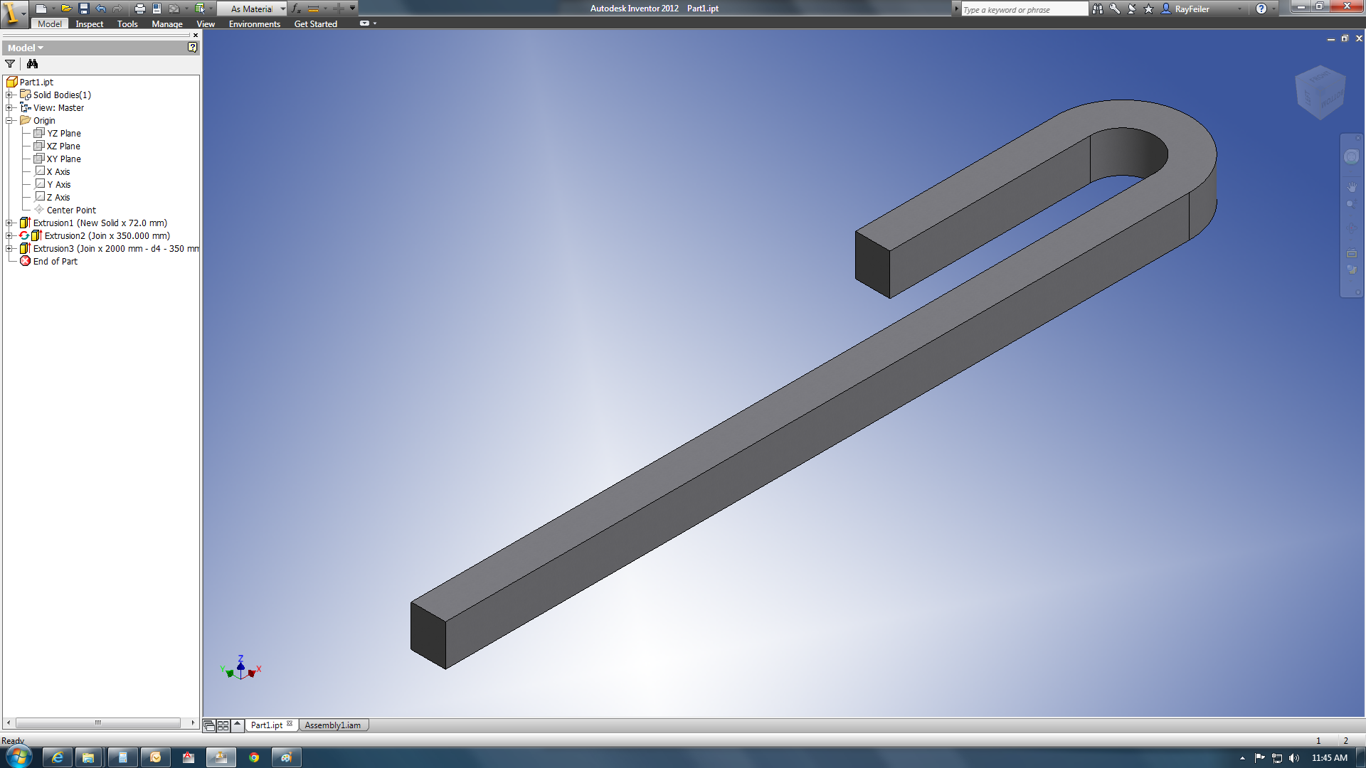
This will work if you rebuild your model with the extrusions normal to the direction of adaptability. With this method you can change Mate1 in my example but you cannot drive it. Sorry I can only upload IV2012 data.
Product Design & Manufacturing Collection 2024
Sometimes you just need a good old reboot.
Message 8 of 14
03-15-2012
08:53 AM
- Mark as New
- Bookmark
- Subscribe
- Mute
- Subscribe to RSS Feed
- Permalink
- Report
03-15-2012
08:53 AM
The assembly.
Product Design & Manufacturing Collection 2024
Sometimes you just need a good old reboot.
Message 9 of 14
03-15-2012
09:09 AM
- Mark as New
- Bookmark
- Subscribe
- Mute
- Subscribe to RSS Feed
- Permalink
- Report
03-15-2012
09:09 AM
if I was to drop that long part into an assembly, I could not right click on it in the browser and tick the "Flexible" option as it will not be there due to it being a part (.ipt).
You attached an assembly.
-----------------------------------------------------------------------------------------
Autodesk Inventor 2019 Certified Professional
Autodesk AutoCAD 2013 Certified Professional
Certified SolidWorks Professional
Message 10 of 14
03-15-2012
09:14 AM
- Mark as New
- Bookmark
- Subscribe
- Mute
- Subscribe to RSS Feed
- Permalink
- Report
03-15-2012
09:14 AM
@Anonymous wrote:if I was to drop that long part into an assembly, I could not right click on it in the browser and tick the "Flexible" option as it will not be there due to it being a part (.ipt).
You attached an assembly.
I think we are getting confused here. I attached the assembly with two plates. The actual application I will be using it in is a sliding door mechanism. I did this because the size of the assembly is massive, and wouldn't be able to be attached. The upper plate is to represent the steelwork, the lower plate is to represent the sliding door. The information I gain from this thread would be used to implement the runner in the sliding door assembly. I would just be placing the long part (.ipt) into the assembly with the steelwork and the door.
Message 11 of 14
03-15-2012
09:17 AM
- Mark as New
- Bookmark
- Subscribe
- Mute
- Subscribe to RSS Feed
- Permalink
- Report
03-15-2012
09:17 AM
@Anonymous wrote:This will work if you rebuild your model with the extrusions normal to the direction of adaptability. With this method you can change Mate1 in my example but you cannot drive it. Sorry I can only upload IV2012 data.
Driving it is what I need for this assembly. I appreciate the method you have used though.
Message 12 of 14
03-15-2012
09:27 AM
- Mark as New
- Bookmark
- Subscribe
- Mute
- Subscribe to RSS Feed
- Permalink
- Report
03-15-2012
09:27 AM
I have tried a few other methods but none of them would allow me to drive the adaptive part. Does anyone know if this is possible inside of Inventor?
Product Design & Manufacturing Collection 2024
Sometimes you just need a good old reboot.
Message 13 of 14
03-15-2012
01:28 PM
- Mark as New
- Bookmark
- Subscribe
- Mute
- Subscribe to RSS Feed
- Permalink
- Report
03-15-2012
01:28 PM
edit
Apologies, I've just re-read you post and you have done as I suggested.
Can't explain why it would work in one assembly but not in another,all things being equal.
So ignore the following.
You have done all the work.
One edit is needed to make it drive.
1. Delete origin to curve centre constraint.
2. Constrain end point of cable to origin.
3. Drive flush constraint between block parts, with adaptivity ticked on.
Done.


Message 14 of 14
03-16-2012
02:09 AM
- Mark as New
- Bookmark
- Subscribe
- Mute
- Subscribe to RSS Feed
- Permalink
- Report
03-16-2012
02:09 AM
Thank you so much!
That was the reason why it didn't work in the sliding doors, I used a "Mate" instead of a "Flush" constraint! I can't believe that a flush will work where a mate doesn't, it's quite confusing!
But that's great, thank you so much.
And everyone else who contributed, all the other posts helped me too!
Thanks everyone! Hopefully this will be a good example for people to read through in the future.
Reply
Topic Options
- Subscribe to RSS Feed
- Mark Topic as New
- Mark Topic as Read
- Float this Topic for Current User
- Bookmark
- Subscribe
- Printer Friendly Page
Forums Links
Can't find what you're looking for? Ask the community or share your knowledge.
Post to forums
