Community
Inventor Forum
Welcome to Autodesk’s Inventor Forums. Share your knowledge, ask questions, and explore popular Inventor topics.
Turn on suggestions
Auto-suggest helps you quickly narrow down your search results by suggesting possible matches as you type.
Reply
Topic Options
- Subscribe to RSS Feed
- Mark Topic as New
- Mark Topic as Read
- Float this Topic for Current User
- Bookmark
- Subscribe
- Printer Friendly Page
Message 1 of 12
Anonymous
2216 Views, 11 Replies
04-09-2012
10:09 AM
- Mark as New
- Bookmark
- Subscribe
- Mute
- Subscribe to RSS Feed
- Permalink
- Report
04-09-2012
10:09 AM
Isometric Shaft Dimension
Trying to dimension a shaft in isometric view with various diameters. I am unable to find or select the centerpoints at the ends of the shaft. This causes dimensions to be crooked. How can i get the centerpoints to display so that they may be selected?
11 REPLIES 11
Message 2 of 12
04-09-2012
10:48 AM
- Mark as New
- Bookmark
- Subscribe
- Mute
- Subscribe to RSS Feed
- Permalink
- Report
04-09-2012
10:48 AM
Hi KyleMJewell,
If you select the arcs with the General Dimension tool you should get the result you're after (be sure not to select the green dots though). Note that you can use the Space bar to toggle through the avalable placement planes.
The green dots are object snaps. If you start the General Dimension tool and then right-click you should see a Snap Settings flyout menu, where you can control which snaps show up. But I don't you need to adjust these in this particular case.
I hope this helps.
Best of luck to you in all of your Inventor pursuits,
Curtis
http://inventortrenches.blogspot.com

 >>>
>>>
Message 3 of 12
04-09-2012
11:04 AM
- Mark as New
- Bookmark
- Subscribe
- Mute
- Subscribe to RSS Feed
- Permalink
- Report
04-09-2012
11:04 AM
Hi KyleMJewell,
Also, once you've selected an arc you can right-click to find the Diameter and Use Sheet Plane options for the diameter dims.
I hope this helps.
Best of luck to you in all of your Inventor pursuits,
Curtis
http://inventortrenches.blogspot.com


Message 4 of 12
04-09-2012
11:11 AM
- Mark as New
- Bookmark
- Subscribe
- Mute
- Subscribe to RSS Feed
- Permalink
- Report
04-09-2012
11:11 AM
This method works if there is no modification to the shaft such as the threads or woodruff keyseat which prevent it from automatically recognizing centerpoints. I have tried several times and it still does not work.
Message 5 of 12
04-09-2012
11:14 AM
- Mark as New
- Bookmark
- Subscribe
- Mute
- Subscribe to RSS Feed
- Permalink
- Report
04-09-2012
11:14 AM
Hi KyleMJewell,
Can you provide us an example part file that demonstrates the issue you're seeing?
I hope this helps.
Best of luck to you in all of your Inventor pursuits,
Curtis
http://inventortrenches.blogspot.com
Message 6 of 12
04-09-2012
11:22 AM
- Mark as New
- Bookmark
- Subscribe
- Mute
- Subscribe to RSS Feed
- Permalink
- Report
04-09-2012
11:22 AM
Here is the part that I am having trouble with dimensioning. You may notice that the thread is coil cut because I needed it created that way.
Message 7 of 12
04-09-2012
01:27 PM
- Mark as New
- Bookmark
- Subscribe
- Mute
- Subscribe to RSS Feed
- Permalink
- Report
04-09-2012
01:27 PM
Hi KyleMJewell,
You're correct it is the coil cuts that are causing the issue, since they result in an edge that isn't a true arc. Unfortunately, I didn't really see an easy solution to placing those dimensions in that view. The best I could do was to turn on the hidden lines and scrub over each edge until I located the (very tiny) edge that was an arc, and then I used that to find the center point. Then I turned off the hidden lines.
I'm not sure that provides a very robust solution, but it did work.
I hope this helps.
Best of luck to you in all of your Inventor pursuits,
Curtis
http://inventortrenches.blogspot.com
Message 8 of 12
Anonymous
in reply to:
Anonymous
04-09-2012
01:45 PM
- Mark as New
- Bookmark
- Subscribe
- Mute
- Subscribe to RSS Feed
- Permalink
- Report
04-09-2012
01:45 PM
Out of curiousity have you tried putting work points on your part prior to any modification cuts, then bringing those work points into the drawing for the dimensioning and either switching them to a different point style or turning them off after your dimension is set.
It should be a bit more 'robust' for future changes in length and you have points at the centers that can be used. I have always found that though a face/feature may change drastically if I put a work point at the right step my part will be extremely robust and almost impossible to break, the dimensions on drawings rarely drop out for that matter on the finer details.
Message 10 of 12
04-20-2012
08:29 AM
- Mark as New
- Bookmark
- Subscribe
- Mute
- Subscribe to RSS Feed
- Permalink
- Report
04-20-2012
08:29 AM
Curtis,
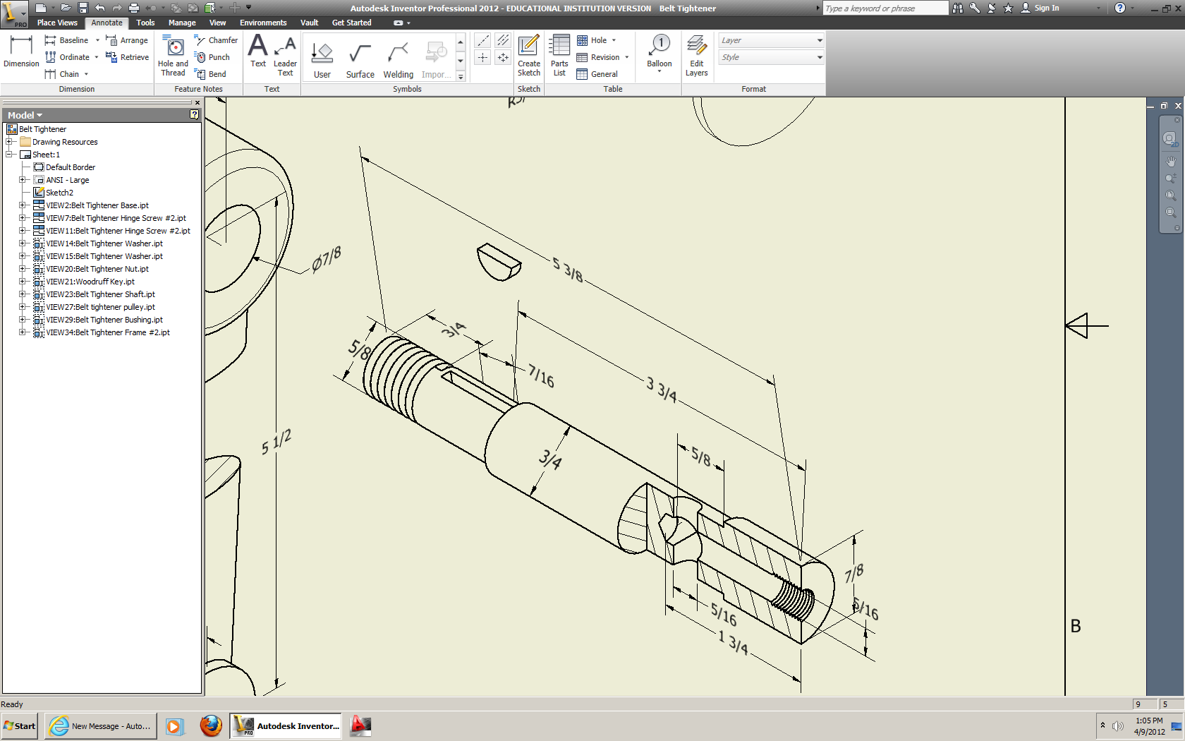
Does this only work with Radius or Diameter dimensions? In the picture below, I'd like to get the notes and linear dimensions onto the same plane... one or the other, I have no preference which.

Chris Benner
Inventor Tube & Pipe, Vault Professional
Cad Tips Tricks & Workarounds | Twitter | LinkedIn
Autodesk University Classes:
Going With The Flow with Inventor Tube and Pipe | Increasing The Volume with Inventor Tube and Pipe | Power of the Autodesk Community | Getting to Know You | Inventor Styles & Standards |Managing Properties with Vault Professional | Vault Configuration | Vault - What is it & Why Do I Need It? | A Little Less Talk - Tube & Pipe Demo | Change Orders & Revisions - Vault, Inventor & AutoCAD | Authoring & Publishing Custom Content
Message 11 of 12
04-20-2012
09:18 AM
- Mark as New
- Bookmark
- Subscribe
- Mute
- Subscribe to RSS Feed
- Permalink
- Report
04-20-2012
09:18 AM
Hi cbenner,
You can set a linear dimension to use the sheet plane, but it won't calculate correctly. But it might work if you overide the value and place notes instead. Or you might be able to place a linear dimension and hide an arrowhead, exension line, etc. to make it look like a leader. But I don't know of a way to get a leader note to park on a model plane.
I suppose you could cheat and place some small circular phantom part in your assembly to use for placement of a diameter dimension and then overide it to use as a leader note. ![]()
I hope this helps.
Best of luck to you in all of your Inventor pursuits,
Curtis
http://inventortrenches.blogspot.com
Message 12 of 12
04-20-2012
09:48 AM
- Mark as New
- Bookmark
- Subscribe
- Mute
- Subscribe to RSS Feed
- Permalink
- Report
04-20-2012
09:48 AM
Thanks Curtis.
Thankfully this is an oddball drawing, and we don't normally do this. I recall back in the horse & buggy days having to create special text styles in AutoCad to do this on isometric drawings for a show and tell. RRRG!
Chris Benner
Inventor Tube & Pipe, Vault Professional
Cad Tips Tricks & Workarounds | Twitter | LinkedIn
Autodesk University Classes:
Going With The Flow with Inventor Tube and Pipe | Increasing The Volume with Inventor Tube and Pipe | Power of the Autodesk Community | Getting to Know You | Inventor Styles & Standards |Managing Properties with Vault Professional | Vault Configuration | Vault - What is it & Why Do I Need It? | A Little Less Talk - Tube & Pipe Demo | Change Orders & Revisions - Vault, Inventor & AutoCAD | Authoring & Publishing Custom Content
Reply
Topic Options
- Subscribe to RSS Feed
- Mark Topic as New
- Mark Topic as Read
- Float this Topic for Current User
- Bookmark
- Subscribe
- Printer Friendly Page
