Community
Inventor Forum
Welcome to Autodesk’s Inventor Forums. Share your knowledge, ask questions, and explore popular Inventor topics.
Turn on suggestions
Auto-suggest helps you quickly narrow down your search results by suggesting possible matches as you type.
Reply
Topic Options
- Subscribe to RSS Feed
- Mark Topic as New
- Mark Topic as Read
- Float this Topic for Current User
- Bookmark
- Subscribe
- Printer Friendly Page
Message 1 of 113
09-02-2011
07:30 PM
- Mark as New
- Bookmark
- Subscribe
- Mute
- Subscribe to RSS Feed
- Permalink
- Report
09-02-2011
07:30 PM
![]()
I would like to be able to move parts/assemblies around in Inventor very quickly but very accurately.
Like you can move something in AutoCAD.
When you go into the move command it would be nice to be able to enter exact x,y or z values for movement.
Maybe it could be added to the "Grip Snap" function where you select an edge on the part or something, or the x,y,z axis and move an inputed distance.
I think it would be beneficial to be able to quickly and accurately move parts around before starting to apply assembly constraints?
I know you can do quite a bit with "Grip Snap" and from iproperties "Current Offset From..." but I'm not sure if it's simple and quick?
Franco
GMT +08:00
GMT +08:00
Solved! Go to Solution.
Solved by SBix26. Go to Solution.
112 REPLIES 112
Message 81 of 113
03-08-2012
09:07 PM
- Mark as New
- Bookmark
- Subscribe
- Mute
- Subscribe to RSS Feed
- Permalink
- Report
03-08-2012
09:07 PM
I would like to suggest the following.
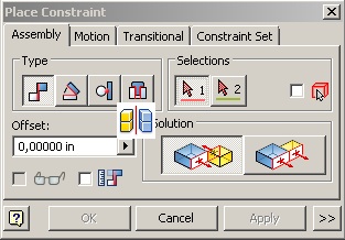
1. 2D Sketch shown that you can select the lines>>right click>>constrain>>[select constrain]
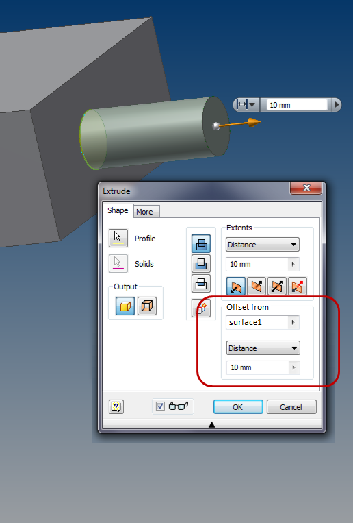
2. 3D model shown that you can offset from the base line to a certain distance.
Message 82 of 113
03-10-2012
09:48 AM
- Mark as New
- Bookmark
- Subscribe
- Mute
- Subscribe to RSS Feed
- Permalink
- Report
03-10-2012
09:48 AM
I have been using Inventor to automate models and assemblies for quite a while, but I find it very difficult to automate drawings. Below is my wish list that could help address this.
1. Have the option of useing the parameters table within the drawing environment. Just like the parameters table in the part and assembly files, be able to link to excel or other ipt or iam files. When creating a dimension in a sketch in a drawing, I would like to see the option of "list parameters".
2. Have groups of dimensions (layers) in drawings that can be suppressed according to parameters. If I have a feature in 1 part that is not in a very similar part, it can suppress the dimensions instead of turning them pink. I imagine this could be similar to the feature properties in an ipt.
3. iLogic- better integration of multi-bodied parts. Getting the volume and surface area of a certain body is not impossible, but it is very difficult.
4. Better documentation on iLogic. It is a powerfull tool, but it is difficult to find support materials for more advanced problems. I don't even know where I can find a list of possible commands.
5. Tsplines in Inventor. The Product Design suite has 3ds Max and Inventor... Tsplines would be a great addition.
6. Better surfacing tools. The more functionality that is added for surfacing, the easier my job becomes. Being able to seamlessly switch between solid and surface is great, but a lot of work is repeated because surface modelling does not have the same functionality as solid modelling. Why can't I extrude a hole in a surface?
If you need any clarification on any of these points, feel free to contact me. alleman (at) thunderheaddesign.net
Thanks,
Thomas
Message 83 of 113
03-15-2012
06:26 AM
- Mark as New
- Bookmark
- Subscribe
- Mute
- Subscribe to RSS Feed
- Permalink
- Report
03-15-2012
06:26 AM
I wish that Inventor 2013+ was truly x64 application and Multi-Core supported.
IT Administrator For:
Inventor 2012 Ultimate, Premium, Standard and Mechanical 2012
Message 84 of 113
03-15-2012
07:03 AM
- Mark as New
- Bookmark
- Subscribe
- Mute
- Subscribe to RSS Feed
- Permalink
- Report
03-15-2012
07:03 AM
May seem small but it would be nice to have sub folders in the templates folder. When I do this now, it does not show the sub-folders in templates (even with Inventor files in them).....
JSC
Message 85 of 113
03-15-2012
09:04 AM
- Mark as New
- Bookmark
- Subscribe
- Mute
- Subscribe to RSS Feed
- Permalink
- Report
03-15-2012
09:04 AM
For 1. just hit the little pencil icon in the edit dimension dialog, that takes you to the format text dialog where you can use the parameters. (I use it mainly for bolt circle diameters, except in the hole note you have to exit the edit hole note dialog and right click to select "Text ...")
For 2. I don't understand why you would want to just suppress a dimension to something that does not exist.
My personal wish is that things would work the same across environments. For instance a feature pattern created in an assembly or sub assembly can't be used when patterning parts; using a parameter in a dimension is fine in a part but always results in a "cyclical dependency" in an assembly, and just plain pukes a sketch in a drawing (say, for a title block etc. or otherwise); etc..
Message 86 of 113
03-15-2012
11:13 AM
- Mark as New
- Bookmark
- Subscribe
- Mute
- Subscribe to RSS Feed
- Permalink
- Report
03-15-2012
11:13 AM
I'm still on 2010, so maybe they fixed this bug in 2011, 2012, or 2013? If not; here's hoping for 2014!
KState92
Inventor Professional 2020
AutoCAD Mechanical 2022.0.1
Windows 10 Pro 64 bit - 1903
Core i7-8700 32 GB Ram
Quadro P2000
Inventor Professional 2020
AutoCAD Mechanical 2022.0.1
Windows 10 Pro 64 bit - 1903
Core i7-8700 32 GB Ram
Quadro P2000
Message 87 of 113
03-15-2012
11:17 AM
- Mark as New
- Bookmark
- Subscribe
- Mute
- Subscribe to RSS Feed
- Permalink
- Report
03-15-2012
11:17 AM
This should be changed to 2014 wish list as 2013 is already set in stone and has been for months. Heck it should be available in just a few weeks..
-------------------------------------------------------------------------------------------
Inventor 2023 - Dell Precision 5570
Did you find this reply helpful ? If so please use the Accept Solution button below.
Maybe buy me a beer through Venmo @mcgyvr1269
Message 88 of 113
03-20-2012
11:24 AM
- Mark as New
- Bookmark
- Subscribe
- Mute
- Subscribe to RSS Feed
- Permalink
- Report
03-20-2012
11:24 AM
I would like to have a new Inventor assembly constraint of symmetry. This constraint would work with the origins of selected parts or assemblies (2 entities) and a middle plane selected for the symmetry.
Message 89 of 113
03-20-2012
12:14 PM
- Mark as New
- Bookmark
- Subscribe
- Mute
- Subscribe to RSS Feed
- Permalink
- Report
03-20-2012
12:14 PM
"I would like to have a new Inventor assembly constraint of symmetry. This constraint would work with the origins of selected parts or assemblies (2 entities) and a middle plane selected for the symmetry."
This was one of my big gripes switching from SW to IV. If you ever mate in SW you'll be mad at AutoDesk for falling so far behind in mate functionality.
Mike (not Matt) Rattray

Message 91 of 113
03-21-2012
12:50 PM
- Mark as New
- Bookmark
- Subscribe
- Mute
- Subscribe to RSS Feed
- Permalink
- Report
03-21-2012
12:50 PM
For the Break fonction In a drawing .idw, I wish we could edit the break line as we can for a Section Line.
Message 92 of 113
03-21-2012
12:52 PM
- Mark as New
- Bookmark
- Subscribe
- Mute
- Subscribe to RSS Feed
- Permalink
- Report
03-21-2012
12:52 PM
@nicolaslegare wrote:For the Break fonction In a drawing .idw, I wish we could edit the break line as we can for a Section Line.
SO SAY WE ALL.
KState92
Inventor Professional 2020
AutoCAD Mechanical 2022.0.1
Windows 10 Pro 64 bit - 1903
Core i7-8700 32 GB Ram
Quadro P2000
Inventor Professional 2020
AutoCAD Mechanical 2022.0.1
Windows 10 Pro 64 bit - 1903
Core i7-8700 32 GB Ram
Quadro P2000
Message 93 of 113
03-21-2012
01:01 PM
- Mark as New
- Bookmark
- Subscribe
- Mute
- Subscribe to RSS Feed
- Permalink
- Report
03-21-2012
01:01 PM
In a drawing .idw, I wish we could link the scale of the sketch symbol with the view attached and also put constraints between sketch symbols lines and view lines In a way that sketch symbols will fallow the view with precision.
Message 94 of 113
03-22-2012
07:52 AM
- Mark as New
- Bookmark
- Subscribe
- Mute
- Subscribe to RSS Feed
- Permalink
- Report
03-22-2012
07:52 AM
Are we talking about being able to put jogs in the line, or just being able to do things like put constraints on it (so that if something changes in the model it doesn't slide off the edge so there's no way to find it to try and get it back where it should have stayed and the only thing you can do is delete the whole view and start over again.)
Message 95 of 113
03-23-2012
01:59 PM
- Mark as New
- Bookmark
- Subscribe
- Mute
- Subscribe to RSS Feed
- Permalink
- Report
03-23-2012
01:59 PM
I could probably come up with a bunch, but one that come to mind is in drawings the ability to not only attach text to the balloons, but to show the quantity outside of the balloon in all four quandrants (12,3,6,9 o'clock) and be able to have an "X" after it. Similar to how Solidworks does it.
Best Regards,
Scott McFadden
(Colossians 3:23-25)
Scott McFadden
(Colossians 3:23-25)
Message 96 of 113
06-12-2012
07:44 AM
- Mark as New
- Bookmark
- Subscribe
- Mute
- Subscribe to RSS Feed
- Permalink
- Report
06-12-2012
07:44 AM
Lesoux, it was already implemented in Inventor 2013.
My wish list includes sheet metal features such as normal cut and the possibility to change a base view to a flat partern after projected view is created. Changes in Base view would not affect projected views. I also would need a partial depth view to the projected view so that we could only see some of the bendings.
Message 97 of 113
06-12-2012
08:11 AM
- Mark as New
- Bookmark
- Subscribe
- Mute
- Subscribe to RSS Feed
- Permalink
- Report
06-12-2012
08:11 AM
Should be ability to create the slots (straight slot, arc slot) like separate feature in the sketch. Creating slots like 2 circle and 2 line or arc with constraints is too long.
Win10 x64
Xeon E5-1630
32 Gb RAM
Quadro K5200
Inventor 2020.3.4, Build 373
Xeon E5-1630
32 Gb RAM
Quadro K5200
Inventor 2020.3.4, Build 373
Message 98 of 113
06-12-2012
08:27 AM
- Mark as New
- Bookmark
- Subscribe
- Mute
- Subscribe to RSS Feed
- Permalink
- Report
06-12-2012
08:27 AM
I disagree with that last one. You can create a slot very easily with just the line tool and no need to use circles.
Did you find this reply helpful ? If so please use the Accept as Solution or Kudos button below.
Mark Flayler - Engagement Engineer
IMAGINiT Manufacturing Solutions Blog: https://resources.imaginit.com/manufacturing-solutions-blog
Message 99 of 113
06-12-2012
08:40 AM
- Mark as New
- Bookmark
- Subscribe
- Mute
- Subscribe to RSS Feed
- Permalink
- Report
06-12-2012
08:40 AM
I know about this way. It works for linear slots only. Tell me please, how you will create the arc slots? I'm talking about separate feature with creating dimensions automatically.
Win10 x64
Xeon E5-1630
32 Gb RAM
Quadro K5200
Inventor 2020.3.4, Build 373
Xeon E5-1630
32 Gb RAM
Quadro K5200
Inventor 2020.3.4, Build 373
Message 100 of 113
06-12-2012
09:08 AM
- Mark as New
- Bookmark
- Subscribe
- Mute
- Subscribe to RSS Feed
- Permalink
- Report
06-12-2012
09:08 AM
Seperate sketch element or seperate feature?
I usually sketch it out, but if I wanted a feature I would use the Place Feature command.

Did you find this reply helpful ? If so please use the Accept as Solution or Kudos button below.
Mark Flayler - Engagement Engineer
IMAGINiT Manufacturing Solutions Blog: https://resources.imaginit.com/manufacturing-solutions-blog
Reply
Topic Options
- Subscribe to RSS Feed
- Mark Topic as New
- Mark Topic as Read
- Float this Topic for Current User
- Bookmark
- Subscribe
- Printer Friendly Page
