Community
- Forums Home
- >
- Inventor Community
- >
- Inventor Forum
- >
- Re: How to generate a guide rail to control twist
Inventor Forum
Welcome to Autodesk’s Inventor Forums. Share your knowledge, ask questions, and explore popular Inventor topics.
Turn on suggestions
Auto-suggest helps you quickly narrow down your search results by suggesting possible matches as you type.
Reply
Topic Options
- Subscribe to RSS Feed
- Mark Topic as New
- Mark Topic as Read
- Float this Topic for Current User
- Bookmark
- Subscribe
- Printer Friendly Page
Message 1 of 6
09-18-2012
12:00 PM
- Mark as New
- Bookmark
- Subscribe
- Mute
- Subscribe to RSS Feed
- Permalink
- Report
09-18-2012
12:00 PM
Hello,
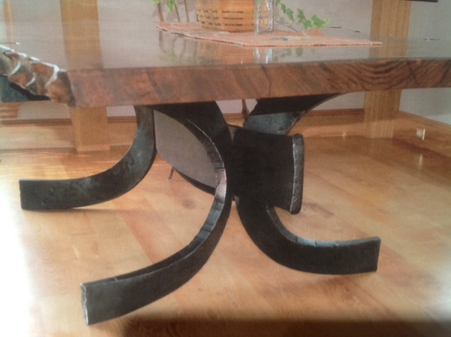
I am trying to model a forged steel table base so I can create some tooling to reproduce it. See the attached photo of the base. I am able to sweep along my 3D projected sketch path but there is a twist at the center that I believe I need a guide rail to control. I have tried to draw a rail but it fails. I suspect I am not drawing my guide rail correctly as to create the slight twist. Any suggestions? I was considering drawing a shallow helix along the 3d sweep path but not sure that this is the beswt direction to head next. I have attached the .ipt with the sweep (without guide path being used).
Thanks!
AB
Solved! Go to Solution.
Solved by glenn-chun. Go to Solution.
5 REPLIES 5
Message 2 of 6
09-18-2012
12:42 PM
- Mark as New
- Bookmark
- Subscribe
- Mute
- Subscribe to RSS Feed
- Permalink
- Report
09-18-2012
12:42 PM
I noticed your first sketch was not constrained or making use of symmetry about the origin.
You might want to start here http://home.pct.edu/~jmather/SkillsUSA%20University.pdf
Then here and here for information on 3D sketches
http://home.pct.edu/~jmather/content/DSG322/Inventor%20Tutorials/Inventor%2011%20Tutorial%207.pdf
http://home.pct.edu/~jmather/content/DSG322/Inventor%20Tutorials/Inventor%202011%20Tutorial%2014.pdf
-----------------------------------------------------------------------------------------
Autodesk Inventor 2019 Certified Professional
Autodesk AutoCAD 2013 Certified Professional
Certified SolidWorks Professional
Message 3 of 6
09-18-2012
06:21 PM
- Mark as New
- Bookmark
- Subscribe
- Mute
- Subscribe to RSS Feed
- Permalink
- Report
09-18-2012
06:21 PM
I read through the tips, they were really helpful, thank you. I still am confused about the guide paths though. Since my profile is rectangular the bank/ twist is critical and I need to generate a guide path. Any reccomendations here?
Thanks,
AB
Message 4 of 6
09-19-2012
12:05 AM
- Mark as New
- Bookmark
- Subscribe
- Mute
- Subscribe to RSS Feed
- Permalink
- Report
09-19-2012
12:05 AM
Hi Andrew,
See attached IPT. It's far from perfect, but it should give you some idea of how to control twist using a guide rail.


Hope that helps,
Glenn
ASM Development
Glenn Chun
Sr. Principal Engineer
Message 5 of 6
09-19-2012
09:16 AM
- Mark as New
- Bookmark
- Subscribe
- Mute
- Subscribe to RSS Feed
- Permalink
- Report
09-19-2012
09:16 AM
Hi Glenn, Thank you- that was very helpful. How did you create the path and guide rail? It looks like you used your construction lines on the 30, 40 &50cm planes to lay out a free-hand spline. I was trying to create these paths using an intersection curve and had no such luck getting them to be "tangent continuous". Thanks, Andy
Message 6 of 6
09-19-2012
09:58 AM
- Mark as New
- Bookmark
- Subscribe
- Mute
- Subscribe to RSS Feed
- Permalink
- Report
09-19-2012
09:58 AM
@AndrewBeekman9108 wrote:
How did you create the path and guide rail?
Hi Andrew,
I'm glad to hear that it was helpful. In addition to the 30, 40, and 50cm planes, there's an important plane at 60 cm above the floor ("table bot plane" in the browser). Here's what I did:
1. Roughly create free-hand 3D splines for path and guide rail. Each spline starts at a profile point.
2. Create 2D sketch points on the four work planes (Create a set of points on the +X side and then mirror them to the -X side).
3. Include the 2D sketch points in the 3D sketches for path and guide rail (Use "Include Geometry" command).
4. Add coincident constraints between the included points and spline points.
5. Right-click on the start and end points of each spline and select "Activate Handle".
a. Add a parallel constraint between each handle and Z-Axis.
b. Add a dimension to the handle.
6. Right-click on the midpoint of each spline (Each midpoint is located at 60 cm above the floor) and select "Activate Handle".
a. Add a parallel constraint between each handle and X-Axis (I forgot to do that in the attached IPT).
b. Add a dimension to the handle.
There are many different (and better) ways to model the two rails. My method above is just one example.
Glenn
ASM Development
Glenn Chun
Sr. Principal Engineer
Reply
Topic Options
- Subscribe to RSS Feed
- Mark Topic as New
- Mark Topic as Read
- Float this Topic for Current User
- Bookmark
- Subscribe
- Printer Friendly Page
