Community
Inventor Forum
Welcome to Autodesk’s Inventor Forums. Share your knowledge, ask questions, and explore popular Inventor topics.
Turn on suggestions
Auto-suggest helps you quickly narrow down your search results by suggesting possible matches as you type.
Reply
Topic Options
- Subscribe to RSS Feed
- Mark Topic as New
- Mark Topic as Read
- Float this Topic for Current User
- Bookmark
- Subscribe
- Printer Friendly Page
Message 1 of 10
11-07-2013
05:33 PM
- Mark as New
- Bookmark
- Subscribe
- Mute
- Subscribe to RSS Feed
- Permalink
- Report
11-07-2013
05:33 PM
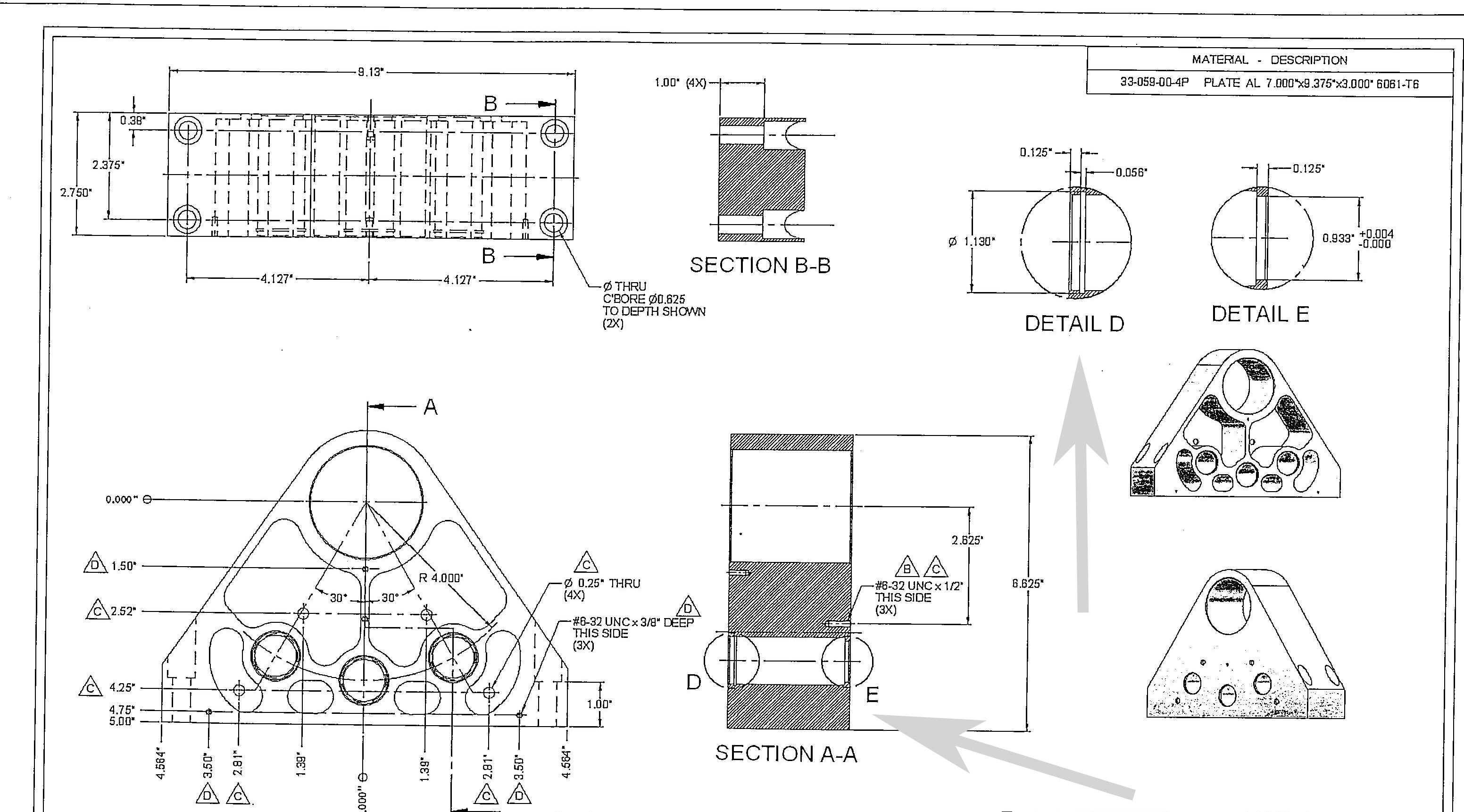
Anybody can show me how to draw this groove from blueprint please.
Solved! Go to Solution.
Solved by JDMather. Go to Solution.
Solved by conklinjm. Go to Solution.
9 REPLIES 9
Message 2 of 10
11-07-2013
05:48 PM
- Mark as New
- Bookmark
- Subscribe
- Mute
- Subscribe to RSS Feed
- Permalink
- Report
11-07-2013
05:48 PM
Looks like a Revolve - Cut to me.
You attached an iam (assembly file).
That drawing looks like it should be an ipt (part file).
An assembly file (*.iam) is only a list of hyperlinks to the part files (*.ipt) and a record of assembly constraints (and a bit more).
You must include the part files.
-----------------------------------------------------------------------------------------
Autodesk Inventor 2019 Certified Professional
Autodesk AutoCAD 2013 Certified Professional
Certified SolidWorks Professional
The CADWhisperer YouTube Channel
Message 3 of 10
11-07-2013
06:49 PM
- Mark as New
- Bookmark
- Subscribe
- Mute
- Subscribe to RSS Feed
- Permalink
- Report
11-07-2013
06:49 PM
In the process I probably open it in the assembly and save it as assembly file ( *.iam) and lost my part file ( *.ipt) can this be revers?
Can you elaborate about in little more then (Revolve-Cut) so I can draw it please.
Message 4 of 10
11-07-2013
08:35 PM
- Mark as New
- Bookmark
- Subscribe
- Mute
- Subscribe to RSS Feed
- Permalink
- Report
11-07-2013
08:35 PM
You dont say what version you are running, here is revolve & extrude example (Can be accomplished in more ways i am sure) using IV2013
Message 5 of 10
11-08-2013
02:16 AM
- Mark as New
- Bookmark
- Subscribe
- Mute
- Subscribe to RSS Feed
- Permalink
- Report
11-08-2013
02:16 AM
@097013309 wrote:
In the process I probably open it in the assembly and save it as assembly file ( *.iam) and lost my part file ( *.ipt) can this be revers?
Can you elaborate about in little more then (Revolve-Cut) so I can draw it please.
You cannot save a part file as an assembly file.
Your part file name is Hinge_Mount.MCNEIL.IPT search your hard drive.
I recommed that you first learn how to set up a project file (*.ipj)
I recommend that you put this aside for a while and go through these
http://home.pct.edu/~jmather/SkillsUSA%20University.pdf
http://inventortrenches.blogspot.com/p/inventor-tutorials.html
http://wikihelp.autodesk.com/enu?adskContextId=HELP_TUTORIALS&language=ENU&release=2014&product=Inve...
-----------------------------------------------------------------------------------------
Autodesk Inventor 2019 Certified Professional
Autodesk AutoCAD 2013 Certified Professional
Certified SolidWorks Professional
The CADWhisperer YouTube Channel
Message 6 of 10
11-08-2013
02:12 PM
- Mark as New
- Bookmark
- Subscribe
- Mute
- Subscribe to RSS Feed
- Permalink
- Report
11-08-2013
02:12 PM
I am running Autodesk Inventor Professional 2014 Student version.
I can't open your file. When I click on attachment Inventor opening it ,but nothing on the screen or browser.
Thank you for answer.
Message 7 of 10
11-08-2013
02:47 PM
- Mark as New
- Bookmark
- Subscribe
- Mute
- Subscribe to RSS Feed
- Permalink
- Report
11-08-2013
02:47 PM
Ok. I find my file and I am attachung itI stiil need advice how to do this groove. Do I should make costruction plane firs? I need surface to put drawing on it ? How I can "go Inside hole" to be able to draw it?
Message 9 of 10
11-08-2013
04:15 PM
- Mark as New
- Bookmark
- Subscribe
- Mute
- Subscribe to RSS Feed
- Permalink
- Report
11-08-2013
04:15 PM
Unfortunately I have an older version of Inventor and cannot open your part; however, I shall try and answer your question.
Yes, depending on how you created the original sketch, you may need to create a construction axis and work plane to create the revolution.
If the original sketch was on the XY plane and the large bore centered at 0,0, you could sketch on the YZ plane. One method is ...
1) Create a new sketch on the YZ plane
2) Project the Z-axis
3) Draw beneath it a parallel centerline
4) Dimension between these two lines (i.e. 4.0 in)
5) Sketch the revolution (should take ten lines -- X.XX x 0.125 / 1.130 x 0.056 / X.XX x Y.YY / 0.933 x 0.125 bore)
6) Apply three diameter dimensions using the centerline (i.e. X.XX, 1.130 & 0.933)
7) Apply collinear constraint between the two X.XX line segments
😎 Apply three length dimensions (i.e. 0.125, 0.056 & 0.125)
9) Project either the top / bottom edge of the raw material or the two ends of the larger circular bore
10) Constrain the two ends of the revolution to either the end points of the projected edge (line to point) or the two circular projections (collinear lines); Note that the length Y.YY is not needed to be dimensioned as the bore will automatically adjust to the width of the raw material due to these projected elements & constraints
11) Finish Sketch
12) Revolve using the cut option
13) Choose a circular Array
14) Pick the Revolution as the 'Feature'
15) Pick the Z-axis as the 'Axis'
16) Set the number to 3, the angle to 60 and the style to dual-direction
HTH
- - - - - - -
Not sure from where the drawing you are using came but, to completely recreate it, you require more information as many dimensions are missing (such as the size of the bore shown as X.XX above).
Message 10 of 10
11-08-2013
04:25 PM
- Mark as New
- Bookmark
- Subscribe
- Mute
- Subscribe to RSS Feed
- Permalink
- Report
11-08-2013
04:25 PM
Open the attached file.
Find the red End of Part marker in the feature browser.
Drag the red EOP marker down feature-by-feature and examine how they were created.
The Revolve feature is one technique.
You should place the origin for the part at the same location as the origin for the ordinate dimensions.
Note that my part sketches are fully defined.
-----------------------------------------------------------------------------------------
Autodesk Inventor 2019 Certified Professional
Autodesk AutoCAD 2013 Certified Professional
Certified SolidWorks Professional
The CADWhisperer YouTube Channel
Reply
Topic Options
- Subscribe to RSS Feed
- Mark Topic as New
- Mark Topic as Read
- Float this Topic for Current User
- Bookmark
- Subscribe
- Printer Friendly Page
