Community
- Forums Home
- >
- Inventor Community
- >
- Inventor Forum
- >
- Centrifugal force applied to a pendulum in dynamic simulation
Inventor Forum
Welcome to Autodesk’s Inventor Forums. Share your knowledge, ask questions, and explore popular Inventor topics.
Turn on suggestions
Auto-suggest helps you quickly narrow down your search results by suggesting possible matches as you type.
Centrifugal force applied to a pendulum in dynamic simulation
14 REPLIES 14
SOLVED
Reply
Topic Options
- Subscribe to RSS Feed
- Mark Topic as New
- Mark Topic as Read
- Float this Topic for Current User
- Bookmark
- Subscribe
- Printer Friendly Page
Message 1 of 15
Anonymous
2249 Views, 14 Replies
10-05-2012
01:02 AM
- Mark as New
- Bookmark
- Subscribe
- Mute
- Subscribe to RSS Feed
- Permalink
- Report
10-05-2012
01:02 AM
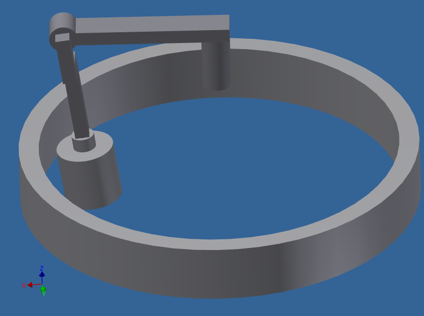
Hi guys, i am new here on the forum, but not new with Inventor. Version i work with is 2011. I want to make Inventor calculate for me the force by which the pendulum acts towards the die ring, which is grounded. In my simulation, i defined material properties of all the parts, gravity, motion around vertical axis is set to constant value. It turns nicely. But, i can not set the die ring to be the position limiting factor to my pendulum and i can not make centrifugal force created by rotation to act on the pendulum. I attach picture of model, which i created to test if this works. Thanks a lot if someone come up with something.
madduk
Solved! Go to Solution.
Solved by henderh. Go to Solution.
14 REPLIES 14
Message 2 of 15
10-05-2012
04:10 AM
- Mark as New
- Bookmark
- Subscribe
- Mute
- Subscribe to RSS Feed
- Permalink
- Report
10-05-2012
04:10 AM
What book are you using to learn Dynamic Simulation?
Can you attach your assembly here?
-----------------------------------------------------------------------------------------
Autodesk Inventor 2019 Certified Professional
Autodesk AutoCAD 2013 Certified Professional
Certified SolidWorks Professional
Message 3 of 15
10-05-2012
04:38 AM
- Mark as New
- Bookmark
- Subscribe
- Mute
- Subscribe to RSS Feed
- Permalink
- Report
10-05-2012
04:38 AM
Hi and thank you for the answer. I do have "Up and Running with Autodesk Inventor Simulation 2011" and "Mastering Autodesk Inventor 2010". I attach the assy here.
Message 4 of 15
10-05-2012
05:35 AM
- Mark as New
- Bookmark
- Subscribe
- Mute
- Subscribe to RSS Feed
- Permalink
- Report
10-05-2012
05:35 AM
I don't think either of those books cover Dynamic Simulation (in any detail), I was thinking more of Wasim Younis book http://www.amazon.com
-----------------------------------------------------------------------------------------
Autodesk Inventor 2019 Certified Professional
Autodesk AutoCAD 2013 Certified Professional
Certified SolidWorks Professional
Message 6 of 15
10-05-2012
08:22 AM
- Mark as New
- Bookmark
- Subscribe
- Mute
- Subscribe to RSS Feed
- Permalink
- Report
10-05-2012
08:22 AM
Yes, but I'm not sure your problem is covered in the book.
I haven't had chance to experiment with your problem.
If you don't have money to purchase the book or if this is your only real need (to solve this particular problem) you might wait a couple of days and see if someone posts a solution (Fridays are usually slow).
-----------------------------------------------------------------------------------------
Autodesk Inventor 2019 Certified Professional
Autodesk AutoCAD 2013 Certified Professional
Certified SolidWorks Professional
Message 7 of 15
10-05-2012
09:17 AM
- Mark as New
- Bookmark
- Subscribe
- Mute
- Subscribe to RSS Feed
- Permalink
- Report
10-05-2012
09:17 AM
It is not a problem to buy some book, if i know there is an sollution in there. I will look if i can find some other book related to this topic. I am still working on that one and won't stop till i get it right. Will use that more than once.Thanks for answer.
Message 8 of 15
10-05-2012
11:01 AM
- Mark as New
- Bookmark
- Subscribe
- Mute
- Subscribe to RSS Feed
- Permalink
- Report
10-05-2012
11:01 AM
Hi Madduk,
There are a couple different ways to go about it. The easiest way is to disable the zero deg/s^2 acceleration imposed motion in Revolution:1. Then you can see the ~63.9 N rolling force between the cylinder and ring.
I also re-constrained the simulation a little bit by removing the zero acceleration imposed motion in Revolution:1, disabled the rolling joint and replaced it with a 2D contact joint between the roller and outer ring. There you can see the contact (action / reaction) force calculated as ~64 Newtons (assembly attached).
Hope this helps! Please let us know if you have any additional questions, comments or suggestions.
Best regards, -Hugh


Hugh Henderson
QA Engineer (Fusion Simulation)
Message 9 of 15
10-05-2012
11:05 AM
- Mark as New
- Bookmark
- Subscribe
- Mute
- Subscribe to RSS Feed
- Permalink
- Report
10-05-2012
11:05 AM
At first when you mentioned pendulum, and had the zero acceleration imposed motion, I thought you wanted to know the reaction force at the center of rotation due to the centrifugal load of the spinning components. I did a hand calculation and arrived at the same value as DS (158.1 N). You can view the X or Y component of the Revolution :2 joint and see it matches exactly (images attached) ![]()
Warm regards, -Hugh
Hugh Henderson
QA Engineer (Fusion Simulation)
Message 10 of 15
10-08-2012
12:42 AM
- Mark as New
- Bookmark
- Subscribe
- Mute
- Subscribe to RSS Feed
- Permalink
- Report
10-08-2012
12:42 AM
Hi Henderh,
many thanks for your reply. I woul never imagine i could get one like this. Only when i try to open assemblies posted by you, i get Error message saying: "Error in reading RSe stream" so it won't open them. Is there any way to get over this? Another thing, i found out, that you impose motion also on revolution:2 by that little green cross near the joint sign. What motion you impose? Thanks
Madduk
Message 11 of 15
Anonymous
in reply to:
Anonymous
10-08-2012
04:33 AM
- Mark as New
- Bookmark
- Subscribe
- Mute
- Subscribe to RSS Feed
- Permalink
- Report
10-08-2012
04:33 AM
Please, if you could have a look on attached. This is sort of a assembly with desired proportions. I can not get 2D contact working on this one. Thanks a lot for your help.
Message 12 of 15
10-08-2012
08:34 AM
- Mark as New
- Bookmark
- Subscribe
- Mute
- Subscribe to RSS Feed
- Permalink
- Report
10-08-2012
08:34 AM
@Anonymous wrote:Hi Henderh,
... i get Error message saying: "Error in reading RSe stream" so it won't open them.
Madduk
You are using 2011 while Hugh saved in 2013. Inventor files are not backward compatible.
I know you stated 2011 in your first post, but you should add this information to your signature.
Are you a student? (students can download 2013 for free from http://www.autodesk.com/edcommunity )
-----------------------------------------------------------------------------------------
Autodesk Inventor 2019 Certified Professional
Autodesk AutoCAD 2013 Certified Professional
Certified SolidWorks Professional
Message 13 of 15
10-08-2012
02:15 PM
- Mark as New
- Bookmark
- Subscribe
- Mute
- Subscribe to RSS Feed
- Permalink
- Report
10-08-2012
02:15 PM
Yea, i will add it in there. I thought it might had been something like that. And no, i am not a student any more. I finished university last year. Now i am working for company in London.
Message 14 of 15
10-08-2012
03:20 PM
- Mark as New
- Bookmark
- Subscribe
- Mute
- Subscribe to RSS Feed
- Permalink
- Report
10-08-2012
03:20 PM
Hi Maaduk,
The second simulation you posted up looks correct to me.
As you've shown, the maximum reaction force on the roll head in the rolling joint is computed by DS as ~96.035 kN.
Summing moments about the pivot point of the roll assembly (Revolution:2), and solving for the reaction force on the roll head comes out to be ~105 kN by my rough hand calculation. (I used the combined CoG of the roll head and roll assembly as the point of application of the centrfugal force)
I trust the Dynamic Simulation numbers more than my rough hand calculation...and this gives me confidence in both results, since they are somewhat close ![]()
Warm regards, -Hugh
[Edit: add photo of hand calc]
Hugh Henderson
QA Engineer (Fusion Simulation)
Message 15 of 15
10-08-2012
03:29 PM
- Mark as New
- Bookmark
- Subscribe
- Mute
- Subscribe to RSS Feed
- Permalink
- Report
10-08-2012
03:29 PM
Hi Henderh,
many thanks for your help. All this was about calculating force by which roll head acts on the ring. We are upsizeing existing device and we would like to know if the bearings are big enough. You helped me a lot.
Martin
Reply
Topic Options
- Subscribe to RSS Feed
- Mark Topic as New
- Mark Topic as Read
- Float this Topic for Current User
- Bookmark
- Subscribe
- Printer Friendly Page
Forums Links
Can't find what you're looking for? Ask the community or share your knowledge.
Post to forums
