Community
Inventor Forum
Welcome to Autodesk’s Inventor Forums. Share your knowledge, ask questions, and explore popular Inventor topics.
Turn on suggestions
Auto-suggest helps you quickly narrow down your search results by suggesting possible matches as you type.
Reply
Topic Options
- Subscribe to RSS Feed
- Mark Topic as New
- Mark Topic as Read
- Float this Topic for Current User
- Bookmark
- Subscribe
- Printer Friendly Page
Message 1 of 12
Anonymous
5277 Views, 11 Replies
01-22-2014
12:22 PM
- Mark as New
- Bookmark
- Subscribe
- Mute
- Subscribe to RSS Feed
- Permalink
- Report
01-22-2014
12:22 PM
CROSS BRAKE/STIFFENING BEND
I have a 16 ga ss part that is essentially a 34x24 rectangle with a 1" flange all the way around. I need to cross brake it with a 1 3/16" stiffening bend. How can I achieve this in inventor?
11 REPLIES 11
Message 2 of 12
01-22-2014
01:13 PM
- Mark as New
- Bookmark
- Subscribe
- Mute
- Subscribe to RSS Feed
- Permalink
- Report
01-22-2014
01:13 PM
hmmp,
this was added (cosmetic) a while back, but now I can't figure out how to do it.
http://forums.autodesk.com/t5/Inventor-General/Sheet-Metal-Cross-Break/td-p/2532778
-----------------------------------------------------------------------------------------
Autodesk Inventor 2019 Certified Professional
Autodesk AutoCAD 2013 Certified Professional
Certified SolidWorks Professional
Message 3 of 12
01-22-2014
01:16 PM
- Mark as New
- Bookmark
- Subscribe
- Mute
- Subscribe to RSS Feed
- Permalink
- Report
01-22-2014
01:16 PM
I got it do do it cosmetically, but it's the who 1 3/16" that the customer is asking for that is giving me trouble. I can only set the angle, and if you ask me a 1 3/16" crossbrake is friggin massive.
Message 4 of 12
01-22-2014
03:06 PM
- Mark as New
- Bookmark
- Subscribe
- Mute
- Subscribe to RSS Feed
- Permalink
- Report
01-22-2014
03:06 PM
@Anonymous wrote:
... but it's the who 1 3/16" that the customer is asking for....
Did you type the wrong word?
It is possible to model the cross break - but doing so will not allow flat pattern of the part.
-----------------------------------------------------------------------------------------
Autodesk Inventor 2019 Certified Professional
Autodesk AutoCAD 2013 Certified Professional
Certified SolidWorks Professional
Message 5 of 12
01-23-2014
05:35 AM
- Mark as New
- Bookmark
- Subscribe
- Mute
- Subscribe to RSS Feed
- Permalink
- Report
01-23-2014
05:35 AM
Yes I did type the wrong word. Or rather I typed the wrong word once, then I only typed part of a different word.
I'm working on modeling the cross brake, and as you said it won't reflect in the flat, but the part should still flatten, correct? All the rest of it will flatten, just not the additional features that represent the crossbrake?
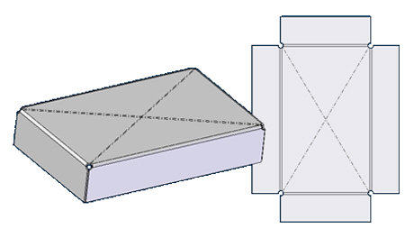
Nevermind, I just did it. Here is my model, let me know what you think about how I achieved it. Thanks for your interest.
Message 6 of 12
01-23-2014
08:05 AM
- Mark as New
- Bookmark
- Subscribe
- Mute
- Subscribe to RSS Feed
- Permalink
- Report
01-23-2014
08:05 AM
Is that going to be stamped? Otherwise I don't know how they'd even break that without the crossbreak going all the way to the corners of the piece where you have your flange.
Jason Yager
Inventor Professional 2023.2
Windows 10 Pro 21H2
Intel(R) Core(TM) i9-10900X CPU @ 3.70GHz
32GB RAM
AMD Radeon Pro WX 3200 Series
3D Connexion SpaceMouse Pro
Inventor Professional 2023.2
Windows 10 Pro 21H2
Intel(R) Core(TM) i9-10900X CPU @ 3.70GHz
32GB RAM
AMD Radeon Pro WX 3200 Series
3D Connexion SpaceMouse Pro
Message 7 of 12
01-23-2014
09:58 AM
- Mark as New
- Bookmark
- Subscribe
- Mute
- Subscribe to RSS Feed
- Permalink
- Report
01-23-2014
09:58 AM
I kept it away from the flange because I didn't want any potential interference. I only modeled the cross breaks to show visually in the drawing views, when it comes to the actual flat, you'll notice that there are cosmetic breaks. And no, usually, in my experience, you keep the ends of the cross breaks away from the part edges/flanges. Usually a good inch or two. I really have no idea why they think they need 1 3/16" cross breaks in this part, but even my supervising press break operator says he won't go that extreme.
So really, that model, I just did for fun. I'd already turned out the part with just cosmetic breaks. I modeled it for fun and to see what I could do.
Message 8 of 12
01-23-2014
11:40 AM
- Mark as New
- Bookmark
- Subscribe
- Mute
- Subscribe to RSS Feed
- Permalink
- Report
01-23-2014
11:40 AM
I'm at a loss how you're cross breaking anything and the break isn't going from edge to edge, even if it was a die the exact length of your break or you were using a box break, you still would get deformation past the break line as the remainder of the metal followed the break motion.
Maybe you guys have some special equipment or process? I've been in a sheet metal shop for 20 years and any cross break I've ever seen, or personally done before I got planted on my butt back here, goes corner to corner/edge to edge. Like your cosmetic break lines in the flat. See attached.
There shouldn't be any interference with the flange because that would be bent after the cross breaks.
Jason Yager
Inventor Professional 2023.2
Windows 10 Pro 21H2
Intel(R) Core(TM) i9-10900X CPU @ 3.70GHz
32GB RAM
AMD Radeon Pro WX 3200 Series
3D Connexion SpaceMouse Pro
Inventor Professional 2023.2
Windows 10 Pro 21H2
Intel(R) Core(TM) i9-10900X CPU @ 3.70GHz
32GB RAM
AMD Radeon Pro WX 3200 Series
3D Connexion SpaceMouse Pro
Message 9 of 12
01-23-2014
12:54 PM
- Mark as New
- Bookmark
- Subscribe
- Mute
- Subscribe to RSS Feed
- Permalink
- Report
01-23-2014
12:54 PM
Yes, you are correct that the cross brake continues on across to the edge of the part. As I said, I wanted to stay away from the edge of the model because I didn't want anything to interfere with the flanges in the model. I was worried about my flat not flattening if I got too close, make sense? It's the first time I modeled a cross brake in Inventor. Normally, I would have just done cometic breaks, but I'm playing with the software. There's really no need to model them up anyways, if it wasn't for the giant size of the crossbreaks i wouldn't have even thought to try.
Never really done a crossbrake at my current job, but at one of my former employer, we'd generally keep the cross break about an inch or so from the part edge. Naturally the deformation continued all the way, kind of transitioned out. Flanges provide ample stiffening around the perimeter, cross brakes are for stiffening toward the middle of a large area to prevent oil canning. Or, if you really want to **** it in the bud, weld on angle iron or channel across it.
Message 10 of 12
02-10-2014
01:21 AM
- Mark as New
- Bookmark
- Subscribe
- Mute
- Subscribe to RSS Feed
- Permalink
- Report
02-10-2014
01:21 AM
I've got a question that follows-up on this conversation. I have a large Stainless steel plate (1200x850 mm, thickness 2 mm) with circumferential holes. To apply some stiffness to this plate a cross break will be added to prevent the plate of swapping from convex to concave shape by gravity.
Now here's the challenge: I'd like to determine the ideal thickness of this plate at which this plate is not going to flip from convex to concave. In real life this (large) plate still flips to the wrong direction under influence of gravity. The Optimization module of Inventor doesn't take the cross-break into account.... Help is greatly appreciated.
Product Design Suite 2024
Inventor 2024 (v 28.20.27200.0000), Vault Basic 2024
Fusion 360
HP Workstation Z4
Intel Xeon 3.4GHz
32GB RAM
Windows 10 Professional (64bit)
Message 11 of 12
03-01-2021
01:16 PM
- Mark as New
- Bookmark
- Subscribe
- Mute
- Subscribe to RSS Feed
- Permalink
- Report
03-01-2021
01:16 PM
I tried that way before but still wouldn't flatten. nice that you figured out my missing step. appreciate it. .j.
Message 12 of 12
03-01-2021
04:05 PM
- Mark as New
- Bookmark
- Subscribe
- Mute
- Subscribe to RSS Feed
- Permalink
- Report
03-01-2021
04:05 PM
Hi! To flatten the shape, your best bet in Inventor is to use Unwrap command. It does not consider material characteristics. It simply flatten any shape.
Many thanks!
Johnson Shiue (johnson.shiue@autodesk.com)
Software Test Engineer
Reply
Topic Options
- Subscribe to RSS Feed
- Mark Topic as New
- Mark Topic as Read
- Float this Topic for Current User
- Bookmark
- Subscribe
- Printer Friendly Page
