Community
Inventor Forum
Welcome to Autodesk’s Inventor Forums. Share your knowledge, ask questions, and explore popular Inventor topics.
Turn on suggestions
Auto-suggest helps you quickly narrow down your search results by suggesting possible matches as you type.
Reply
Topic Options
- Subscribe to RSS Feed
- Mark Topic as New
- Mark Topic as Read
- Float this Topic for Current User
- Bookmark
- Subscribe
- Printer Friendly Page
Message 1 of 22
08-15-2011
10:11 AM
- Mark as New
- Bookmark
- Subscribe
- Mute
- Subscribe to RSS Feed
- Permalink
- Report
08-15-2011
10:11 AM
Hello!
Sitaution: A drawing of a big assembly. In the first (base) view I have colored the parts with different colors.
Question: Can somebody help me with a rule that makes the parts from the projected views to have the some colors from the base view?
Just a simple example:
Part1 - Red
Part2 - Blue
Part3 - Green
So I need the these parts from the projected views to have the same colors . It would really help me a lot, because I spending a lot of time with big assemblies.
Or if it is not that easy to make this kind of rule, give me some tips how should I start and what snippets it should contain. I'm new to iLogic and programming, I found it quite difficult...
Autodesk Inventor 2015 Certified Professional
Solved! Go to Solution.
Solved by Curtis_Waguespack. Go to Solution.
21 REPLIES 21
Message 2 of 22
08-15-2011
07:41 PM
- Mark as New
- Bookmark
- Subscribe
- Mute
- Subscribe to RSS Feed
- Permalink
- Report
08-15-2011
07:41 PM
HI fakeru,
I'm sure it could be done with iLogic, but I'm not sure it needs to.
Unless I've misunderstood, you can setup View Represenations in your assembly to do this, and then set the projected views to use the same View Rep. as the base view.
I hope this helps.
Best of luck to you in all of your Inventor pursuits,
Curtis
http://inventortrenches.blogspot.com

Message 3 of 22
08-16-2011
01:17 AM
- Mark as New
- Bookmark
- Subscribe
- Mute
- Subscribe to RSS Feed
- Permalink
- Report
08-16-2011
01:17 AM
Based on the details from you, could you provide more details how to color the parts in Assembly? Actually there are two ways to color parts -
1. We color the parts with different colors in assembly. When creating base view with shaded style, both of base and project views are colored with the same colors in part. And We can create different presentation views for different colors settings, and the project views are colored with the same colors in base view. Please see the "Shaded.png"
2. We color the parts with different colors in drawing browser. When creating base view, and then change the color within component properties in browser. Please see the "HideLineRemoved.png". If you want to get the project view with the same color in base view, we can leverage the ILogic.
Please let me know what the expected solution you prefer. That I can take the further action.
Thanks,
River Cai
Thanks,
River Cai
Inventor Quality Assurance Team
Autodesk, Inc.
Email: River-Yijiang.Cai@autodesk.com
River Cai
Inventor Quality Assurance Team
Autodesk, Inc.
Email: River-Yijiang.Cai@autodesk.com
Message 4 of 22
08-16-2011
05:25 AM
- Mark as New
- Bookmark
- Subscribe
- Mute
- Subscribe to RSS Feed
- Permalink
- Report
08-16-2011
05:25 AM
I'm with Curtis on this one.. an assembly view rep would accomplish this easily and without the need for any coding.
-------------------------------------------------------------------------------------------
Inventor 2023 - Dell Precision 5570
Did you find this reply helpful ? If so please use the Accept Solution button below.
Maybe buy me a beer through Venmo @mcgyvr1269
Message 5 of 22
08-16-2011
06:00 AM
- Mark as New
- Bookmark
- Subscribe
- Mute
- Subscribe to RSS Feed
- Permalink
- Report
08-16-2011
06:00 AM
Mcgyvr,
I think the OP want to make dwg / idw views with parts in color but not shaded parts, ie normal 2-D line work.
If color in view reps could be translated to line work in the drawing, that would be perfect. But, I don't kow how to accomplish that.
PDSU 2016
Message 6 of 22
08-16-2011
09:08 AM
- Mark as New
- Bookmark
- Subscribe
- Mute
- Subscribe to RSS Feed
- Permalink
- Report
08-16-2011
09:08 AM
@rdyson wrote:Mcgyvr,
I think the OP want to make dwg / idw views with parts in color but not shaded parts, ie normal 2-D line work.
If color in view reps could be translated to line work in the drawing, that would be perfect. But, I don't kow how to accomplish that.
Well then he should have stated that. 🙂 He said he colored the parts..not the lines.
-------------------------------------------------------------------------------------------
Inventor 2023 - Dell Precision 5570
Did you find this reply helpful ? If so please use the Accept Solution button below.
Maybe buy me a beer through Venmo @mcgyvr1269
Message 7 of 22
08-16-2011
09:13 AM
- Mark as New
- Bookmark
- Subscribe
- Mute
- Subscribe to RSS Feed
- Permalink
- Report
08-16-2011
09:13 AM
HI fakeru,
If it is the line color you're asking about, this might helpful:
I hope this helps.
Best of luck to you in all of your Inventor pursuits,
Curtis
http://inventortrenches.blogspot.com
Message 8 of 22
08-16-2011
09:54 AM
- Mark as New
- Bookmark
- Subscribe
- Mute
- Subscribe to RSS Feed
- Permalink
- Report
08-16-2011
09:54 AM
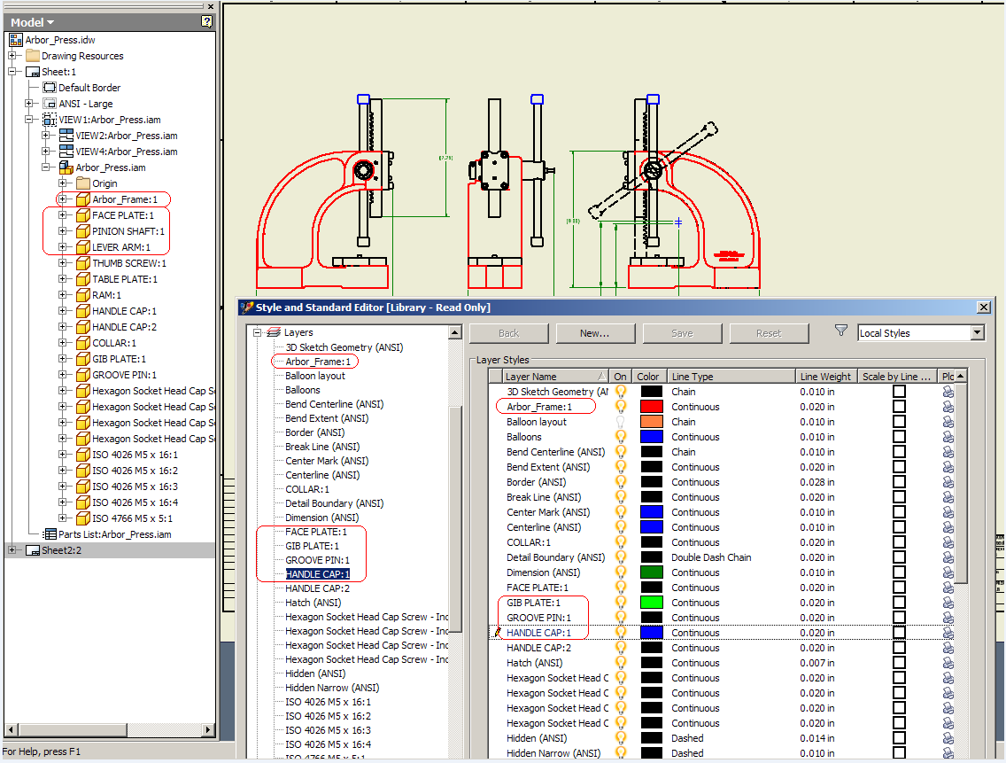
sorry guys for not giving enough details about my question.
So i need to color the parts edges.
This is the way I'm doing it:
1.Select the part from a view (fisrt enable the filter "Select Part Priority ")
2.Right click-->Properties --> Color ---> Choose the color
Here are some screenshots
http://img84.imageshack.us/img84/65/unled3cu.jpg
http://img17.imageshack.us/img17/3948/unled4kj.jpg
http://img804.imageshack.us/img804/3073/11589937.jpg
To understand how much I need the solution check out this screenshot:
http://img198.imageshack.us/img198/2624/13787548.jpg
and this is just medium assembly from my work...
Autodesk Inventor 2015 Certified Professional
Message 9 of 22
08-16-2011
09:59 AM
- Mark as New
- Bookmark
- Subscribe
- Mute
- Subscribe to RSS Feed
- Permalink
- Report
08-16-2011
09:59 AM
Curtis, this is good solution for me! thank you very much!
But there is still a small problem. Some parts I don't need to color, but I if run that macro, all the parts are colored according to assembly color... and none of them will be black (as I never make parts black).
I think the best for me would be that I give the colors in the first view and then the parts properties are copied to others views.
Thanks!
Alexandru
Autodesk Inventor 2015 Certified Professional
Message 10 of 22
08-16-2011
10:33 AM
- Mark as New
- Bookmark
- Subscribe
- Mute
- Subscribe to RSS Feed
- Permalink
- Report
08-16-2011
10:33 AM
Hi fakeru,
I think View Representations will still be a big part of your solution. Rather than manually selecting the components at the drawing level, you should be able to apply color overrides at the assembly level and color your each component just like you want it to apear in the drawing. Then save that as a View Representation that you use in the drawing view(s). This way you can have parts colored as black for the drawing views, but have them as their "real" color in the assembly.
Then you can use Brian Ekin's routine.
I hope this helps.
Best of luck to you in all of your Inventor pursuits,
Curtis
http://inventortrenches.blogspot.com
Message 11 of 22
08-16-2011
11:27 AM
- Mark as New
- Bookmark
- Subscribe
- Mute
- Subscribe to RSS Feed
- Permalink
- Report
08-16-2011
11:27 AM
yes, this may help. I will try this tomorrow in the office.
thanks!
can you please recommend me the best, shortest, easiest way to learn how to make macros and rules. They are quite the same thing, no?
Autodesk Inventor 2015 Certified Professional
Message 12 of 22
08-16-2011
12:02 PM
- Mark as New
- Bookmark
- Subscribe
- Mute
- Subscribe to RSS Feed
- Permalink
- Report
08-16-2011
12:02 PM
HI fakeru,
If you're looking to start with iLogic (which I think is a good place to start) you can use these tutorials:
And here are some examples:
http://inventortrenches.blogspot.com/search/label/Autodesk%20Inventor%20iLogic
If you're looking to work with VBA and Inventor's Application Programing Interface (API), here are a couple of links that should get you started:
... the paper below provides a brief overview of Inventor’s programming interface and illustrates this with examples using iProperties.
| VBA & Inventor API Introduction (zip - 547Kb) |
The following resource will help you get started with programming Inventor. It assumes familiarity with Autodesk Inventor and general programming concepts.
DevTV: Introduction to Inventor Programming
A self-paced video tutorial demonstrating how to get started developing with Autodesk Inventor.
View online | Download
Check out the Self-Paced Guide “My First Plug-in” presented by the ADN Inventor Team
www.autodesk.com/myfirstinventorplugin
I hope this helps.
Best of luck to you in all of your Inventor pursuits,
Curtis
http://inventortrenches.blogspot.com
Message 13 of 22
08-16-2011
08:14 PM
- Mark as New
- Bookmark
- Subscribe
- Mute
- Subscribe to RSS Feed
- Permalink
- Report
08-16-2011
08:14 PM
There is one solution using API code to manage the drawing curves within every component in layer.
For example, there are three components in assebmly and create drawing view, this solution will create three layers in style editor for these three components respectively, and the drawing curves in each view projected from the component will be managed in the layer, and the layer's name is the same with the name of component.
Please copy the code in attached text, and paste it in VBA editor within one new drawing, then save it as one template. When the assembly is done, please create drawing views using this template. When the drawing views are done, please run the Macro and you will see the several layers created in style editor. So you can change the color of layer to change the color of drawing curves, which will keep the parts in all the views colored with the same color.
please see the attached image for more details.
Thanks,
River Cai
Thanks,
River Cai
Inventor Quality Assurance Team
Autodesk, Inc.
Email: River-Yijiang.Cai@autodesk.com
River Cai
Inventor Quality Assurance Team
Autodesk, Inc.
Email: River-Yijiang.Cai@autodesk.com
Message 14 of 22
08-17-2011
09:34 AM
- Mark as New
- Bookmark
- Subscribe
- Mute
- Subscribe to RSS Feed
- Permalink
- Report
08-17-2011
09:34 AM
Unfortunately both scripts don't work properly... Not all the edges are colored (in case of first script) or included in the new layers (in case of the second script). I noticed these edges are tangent edges of the revolution features. In the attachment you can see the screenshot and you will understand. That is a part in the assembly. Any solution?
Autodesk Inventor 2015 Certified Professional
Message 15 of 22
08-17-2011
08:21 PM
- Mark as New
- Bookmark
- Subscribe
- Mute
- Subscribe to RSS Feed
- Permalink
- Report
08-17-2011
08:21 PM
I have seen the attached image, and got the issue you show. This Macro does work fine on R2011, and looks that you are using R2012 now. If yes, this is a known issue, and is not reproducible on R2012 SP1 internal build.
When SP1 is released, please have it packaged for a try.
Thanks,
River Cai
Thanks,
River Cai
Inventor Quality Assurance Team
Autodesk, Inc.
Email: River-Yijiang.Cai@autodesk.com
River Cai
Inventor Quality Assurance Team
Autodesk, Inc.
Email: River-Yijiang.Cai@autodesk.com
Message 16 of 22
08-18-2011
01:10 PM
- Mark as New
- Bookmark
- Subscribe
- Mute
- Subscribe to RSS Feed
- Permalink
- Report
08-18-2011
01:10 PM
yes, I'm using R2012 and there is little chance that I will have SP1 update...
What a shame!![]()
Autodesk Inventor 2015 Certified Professional
Message 17 of 22
10-22-2011
03:03 AM
- Mark as New
- Bookmark
- Subscribe
- Mute
- Subscribe to RSS Feed
- Permalink
- Report
Message 18 of 22
02-07-2012
03:44 PM
- Mark as New
- Bookmark
- Subscribe
- Mute
- Subscribe to RSS Feed
- Permalink
- Report
02-07-2012
03:44 PM
Brian Ekins' code uses the following line to set each collected edge to a colored layer:
Call drawView.Parent.ChangeLayer(objColl, colorLayer
I have a problem with this method, because when I try to set the layer of a certain component, Inventor thinks about it for at least 20 minutes. I don't know if it ever completes the process, because I haven't waited it out. This is just too long. If I just right-click the component (in the browser) and select Properties, I can change the color and linetype (see image) and it works immediately without bogging down.
So my question is, how do I write code to automatically change the properties just like I can do manually? Is there a function I can call instead of ChangeLayer() that will do this, so I don't have to use layers?
Message 19 of 22
02-08-2012
03:51 PM
- Mark as New
- Bookmark
- Subscribe
- Mute
- Subscribe to RSS Feed
- Permalink
- Report
02-08-2012
03:51 PM
So, this is what I came up with:
Spoiler
Dim drawViews As DrawingView
For Each drawViews In ThisApplication.ActiveDocument.ActiveSheet.DrawingViews
occ = drawViews.ReferencedDocumentDescriptor.ReferencedDocument.ComponentDefinition.Occurrences.ItemByName("InsertComponentNameHere")
Dim newColor As Color
newColor = ThisApplication.TransientObjects.CreateColor(0,255,255)
Dim drawcurves As DrawingCurvesEnumerator
drawcurves = drawViews.DrawingCurves(occ)
Dim drawCurve As DrawingCurve
For Each drawCurve In drawcurves
drawCurve.Color() = newColor
Next
Next
This works insofar as it gets around using layers, but I still have the problem of Inventor bogging down changing the color for each edge. What I need to be able to do is write code that will do the same thing as when I right-click a component, choose Properties, and change the component color (rather than right-clicking a component, choosing "Select as edges" and then Properties > change color). When done manually, this only takes a second.
Code gurus: Can this be done? How?
Message 20 of 22
02-09-2012
08:04 AM
- Mark as New
- Bookmark
- Subscribe
- Mute
- Subscribe to RSS Feed
- Permalink
- Report
02-09-2012
08:04 AM
Since this thread has been solved, I decided I really should start a new post here:
Reply
Topic Options
- Subscribe to RSS Feed
- Mark Topic as New
- Mark Topic as Read
- Float this Topic for Current User
- Bookmark
- Subscribe
- Printer Friendly Page
Forums Links
Can't find what you're looking for? Ask the community or share your knowledge.
Post to forums
