Community
Inventor Forum
Welcome to Autodesk’s Inventor Forums. Share your knowledge, ask questions, and explore popular Inventor topics.
Turn on suggestions
Auto-suggest helps you quickly narrow down your search results by suggesting possible matches as you type.
Reply
Topic Options
- Subscribe to RSS Feed
- Mark Topic as New
- Mark Topic as Read
- Float this Topic for Current User
- Bookmark
- Subscribe
- Printer Friendly Page
Message 1 of 20
04-26-2012
01:46 AM
- Mark as New
- Bookmark
- Subscribe
- Mute
- Subscribe to RSS Feed
- Permalink
- Report
04-26-2012
01:46 AM
Spiral stair..
I wish to create a spiral stair but I'm locked here.. I've created the path which is a helix and the feature.. Which command is recommended to follow the helix path?
Thanks for any suggestion!
Revit MEP - Electrical Certified Professional
Revit MEP - Mechanical Certified Professional
Draftworks.wordpress.com
Revit MEP - Mechanical Certified Professional
Draftworks.wordpress.com
19 REPLIES 19
Message 2 of 20
04-26-2012
03:20 AM
- Mark as New
- Bookmark
- Subscribe
- Mute
- Subscribe to RSS Feed
- Permalink
- Report
Message 3 of 20
04-26-2012
04:11 AM
- Mark as New
- Bookmark
- Subscribe
- Mute
- Subscribe to RSS Feed
- Permalink
- Report
04-26-2012
04:11 AM
Rectangular Pattern.
Rather than attaching an image file - attach the Inventor file here.
-----------------------------------------------------------------------------------------
Autodesk Inventor 2019 Certified Professional
Autodesk AutoCAD 2013 Certified Professional
Certified SolidWorks Professional
Message 4 of 20
04-26-2012
04:45 AM
- Mark as New
- Bookmark
- Subscribe
- Mute
- Subscribe to RSS Feed
- Permalink
- Report
04-26-2012
04:45 AM
The "wierd thing" is that this assembly/part must be fully compatible with AutoCAD (2008>2011) as if was built there. I wish to avoid complex techniques to build this stair due compatibility reasons.. I'm using Inventor 2012 Pro.
Revit MEP - Electrical Certified Professional
Revit MEP - Mechanical Certified Professional
Draftworks.wordpress.com
Revit MEP - Mechanical Certified Professional
Draftworks.wordpress.com
Message 5 of 20
04-26-2012
05:38 AM
- Mark as New
- Bookmark
- Subscribe
- Mute
- Subscribe to RSS Feed
- Permalink
- Report
04-26-2012
05:38 AM
There is a similar thread here:
http://forums.autodesk.com/t5/Autodesk-Inventor/Spiral-staircase/td-p/2385713
There I got a problem to make it happen in an assembly.
Any help please.
Message 6 of 20
04-26-2012
05:45 AM
- Mark as New
- Bookmark
- Subscribe
- Mute
- Subscribe to RSS Feed
- Permalink
- Report
04-26-2012
05:45 AM


Revit MEP - Electrical Certified Professional
Revit MEP - Mechanical Certified Professional
Draftworks.wordpress.com
Revit MEP - Mechanical Certified Professional
Draftworks.wordpress.com
Message 7 of 20
04-26-2012
05:49 AM
- Mark as New
- Bookmark
- Subscribe
- Mute
- Subscribe to RSS Feed
- Permalink
- Report
04-26-2012
05:49 AM
I am not familiar with analyzing or editing image files in Inventor.
Can you attach Inventor files?
-----------------------------------------------------------------------------------------
Autodesk Inventor 2019 Certified Professional
Autodesk AutoCAD 2013 Certified Professional
Certified SolidWorks Professional
Message 8 of 20
04-26-2012
06:09 AM
- Mark as New
- Bookmark
- Subscribe
- Mute
- Subscribe to RSS Feed
- Permalink
- Report
04-26-2012
06:09 AM
I did on previous post.
Revit MEP - Electrical Certified Professional
Revit MEP - Mechanical Certified Professional
Draftworks.wordpress.com
Revit MEP - Mechanical Certified Professional
Draftworks.wordpress.com
Message 9 of 20
04-26-2012
06:48 AM
- Mark as New
- Bookmark
- Subscribe
- Mute
- Subscribe to RSS Feed
- Permalink
- Report
04-26-2012
06:48 AM
I think I would use Frame Generator for this design.
-----------------------------------------------------------------------------------------
Autodesk Inventor 2019 Certified Professional
Autodesk AutoCAD 2013 Certified Professional
Certified SolidWorks Professional
Message 10 of 20
04-26-2012
06:51 AM
- Mark as New
- Bookmark
- Subscribe
- Mute
- Subscribe to RSS Feed
- Permalink
- Report
04-26-2012
06:51 AM
Sounds easy but I need 100% compatibility (further edit) with AutoCAD product..
Revit MEP - Electrical Certified Professional
Revit MEP - Mechanical Certified Professional
Draftworks.wordpress.com
Revit MEP - Mechanical Certified Professional
Draftworks.wordpress.com
Message 11 of 20
04-26-2012
07:08 AM
- Mark as New
- Bookmark
- Subscribe
- Mute
- Subscribe to RSS Feed
- Permalink
- Report
04-26-2012
07:08 AM
@Secttor wrote:Sounds easy but I need 100% compatibility (further edit) with AutoCAD product..
I don't understand how using Frame Generator changes anything relative to AutoCAD?
Also, I would probably try to simplify a bit (see attach) to make edits easier.
and I noticed that a couple of your sketches were not constrained.
-----------------------------------------------------------------------------------------
Autodesk Inventor 2019 Certified Professional
Autodesk AutoCAD 2013 Certified Professional
Certified SolidWorks Professional
Message 12 of 20
04-26-2012
09:31 AM
- Mark as New
- Bookmark
- Subscribe
- Mute
- Subscribe to RSS Feed
- Permalink
- Report
04-26-2012
09:31 AM
But is there any explanation for this angle that increases as more as I sweep ?

Revit MEP - Electrical Certified Professional
Revit MEP - Mechanical Certified Professional
Draftworks.wordpress.com
Revit MEP - Mechanical Certified Professional
Draftworks.wordpress.com
Message 13 of 20
04-26-2012
10:37 AM
- Mark as New
- Bookmark
- Subscribe
- Mute
- Subscribe to RSS Feed
- Permalink
- Report
04-26-2012
10:37 AM
The angle is caused by the sweep. It is correctly using a mitre at the 90deg corner, but this mitre is causing the twist or angle that you see.
To avoid that, you will need to treat each 'level' as a seperate sweep. You will also need to redraw the profile sketch for each level.
Message 14 of 20
04-26-2012
11:33 PM
- Mark as New
- Bookmark
- Subscribe
- Mute
- Subscribe to RSS Feed
- Permalink
- Report
Message 15 of 20
04-27-2012
06:04 AM
- Mark as New
- Bookmark
- Subscribe
- Mute
- Subscribe to RSS Feed
- Permalink
- Report
04-27-2012
06:04 AM
The sweep is rotating the box because this is the angle that the box needs to be to produce the correct miter cut for the box faces to match. If you want the handrail to run as you have drawn it you will have to fudge the miters as the faces will not line up properly when the handrail is horizontal.
If you want to use a mitered rectangle, I would set the handrail break point onto the quarter landing higher than you have it at the moment so there is a horizontal flat portion either side of the miter. This will then sweep correctly giving you the detail you need, or just use a round tube instead.
Regards
Martin
Inventor 2023
Message 16 of 20
04-27-2012
07:09 AM
- Mark as New
- Bookmark
- Subscribe
- Mute
- Subscribe to RSS Feed
- Permalink
- Report
04-27-2012
07:09 AM
@Martin_Goodland wrote:If you want the handrail to run as you have drawn it you will have to fudge the miters
But if you do it correctly (using Frame Generator or copied Sketch Blocks) as suggested and then cut your miters - no fudging required - just a bit of work. If you do this a lot - the Frame Generator is the way to go (or even for a one-off if you know how to add custom profiles to the Frame Generator). Otherwise copy your Sketch Block and Multiple Sweep and Sculpt or Split to trim the ends (create multibody solids). Then push out the solids if needed.
-----------------------------------------------------------------------------------------
Autodesk Inventor 2019 Certified Professional
Autodesk AutoCAD 2013 Certified Professional
Certified SolidWorks Professional
Message 17 of 20
04-27-2012
08:03 AM
- Mark as New
- Bookmark
- Subscribe
- Mute
- Subscribe to RSS Feed
- Permalink
- Report
04-27-2012
08:03 AM
Hi JD
Have to disagree. In the attached image showing the miter done using frame generator you can clearly see the issue I tried to explain in my previous e-mail. The faces of the miter do not align because of the geometry used on the stair. The 'Fudge' is that to make this into a suitable handrail joint you would need to weld and blend it to make it look neat (and it will still look odd in my opinion). If you use a round tube it will work but for any other shape you should only change direction in one plane at a time to avoid this.
Regards
Martin
Inventor 2023
Message 18 of 20
04-27-2012
08:11 AM
- Mark as New
- Bookmark
- Subscribe
- Mute
- Subscribe to RSS Feed
- Permalink
- Report
04-27-2012
08:11 AM
@Martin_Goodland wrote:... you can clearly see the issue I tried to explain in my previous e-mail.
I didn't take the time to try it. Points out the hand blending required in the field.
In any case - I think it will requre multiple sweeps (and multiple parts out in the field) where I think the op is expecting a single sweep.
-----------------------------------------------------------------------------------------
Autodesk Inventor 2019 Certified Professional
Autodesk AutoCAD 2013 Certified Professional
Certified SolidWorks Professional
Message 19 of 20
04-27-2012
08:34 AM
- Mark as New
- Bookmark
- Subscribe
- Mute
- Subscribe to RSS Feed
- Permalink
- Report
04-27-2012
08:34 AM
I didn't take the time to try it. Points out the hand blending required in the field.
In any case - I think it will require multiple sweeps (and multiple parts out in the field) where I think the op is expecting a single sweep.
I though that was the case which is why I posted the example. I did not want the OP to go off and try re-working the detail in Frame generator or with sketch blocks as advised when the issue is the handrail geometry being used.
Personally I always use the approach of sweeping a rail as a single part. It highlights geometry issues, like this one, and allows them to be easily fixed. Once the geometry is locked down and approved I would break the rail out as needed for a particular job. Powder coated items are usually fully modeled but for a polished handrail often the single swept part with some joint locations is enough for the shop to fabricate from.
Regards
Martin
Inventor 2023
Message 20 of 20
05-01-2012
11:08 PM
- Mark as New
- Bookmark
- Subscribe
- Mute
- Subscribe to RSS Feed
- Permalink
- Report
05-01-2012
11:08 PM
@Secttor wrote:
But is there any explanation for this angle that increases as more as I sweep ?
Hello Secttor,
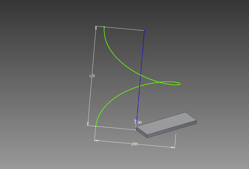
As Martin_Goodland already answered, the profile rotates to produce the correct miter cut for sweep faces to match. The following figure shows how the miter plane is determined between Sketch2 and Sketch3.

As you can see, all faces along Sketch2 perfectly match to all faces along Sketch3 at the miter plane. The top face along Sketch2 is straight up, but the top face along Sketch3 is rotated toward the center of the entire stairs because of the orientation of the miter plane. This top view can help you visualize better:

As Martin_Goodland mentioned, the profile rotations would not cause any orientation issue for the handrail if a circular profile is swept:

If the profile is a square or a round square as shown below, adding a vertical line at the start of each 'level' would resolve the orientation issue for the handrail. A single sweep can make the following model with all top faces 'up'.

HTH,
Glenn
Glenn Chun
Sr. Principal Engineer
Reply
Topic Options
- Subscribe to RSS Feed
- Mark Topic as New
- Mark Topic as Read
- Float this Topic for Current User
- Bookmark
- Subscribe
- Printer Friendly Page
Forums Links
Can't find what you're looking for? Ask the community or share your knowledge.
Post to forums
