Community
Inventor Forum
Welcome to Autodesk’s Inventor Forums. Share your knowledge, ask questions, and explore popular Inventor topics.
Turn on suggestions
Auto-suggest helps you quickly narrow down your search results by suggesting possible matches as you type.
Reply
Topic Options
- Subscribe to RSS Feed
- Mark Topic as New
- Mark Topic as Read
- Float this Topic for Current User
- Bookmark
- Subscribe
- Printer Friendly Page
Message 1 of 15
Anonymous
6015 Views, 14 Replies
07-08-2013
12:20 PM
- Mark as New
- Bookmark
- Subscribe
- Mute
- Subscribe to RSS Feed
- Permalink
- Report
07-08-2013
12:20 PM
Hello,
I've done a lot of reading through these forums and have tried a lot of the suggestions, such as creating lines in a 3D sketch and projecting the geometry to surface, and creating a work plane, and both don't seem to work for me.... I'm trying to cut out a 5.8mmx14mm rectangle out of a cylinder. When I project the geometry to the cylinder's inner surface, I cannot trim the solid in order to extrude.
Please help! I've attached the file.
Thank you,
Nicole
Solved! Go to Solution.
Solved by JDMather. Go to Solution.
14 REPLIES 14
Message 2 of 15
Anonymous
in reply to:
Anonymous
07-08-2013
12:24 PM
- Mark as New
- Bookmark
- Subscribe
- Mute
- Subscribe to RSS Feed
- Permalink
- Report
07-08-2013
12:24 PM
P.S. I'm using Autodesk Inventor 2014... and I'm new to any type of CAD software; I only know the tools/features I know through online tutorials and playing around myself.
Is there some kind of push-pull feature similar to that found in Sketchup Pro so that I can just draw the boundaries of the rectangle on the xy plane (circular plane) of the cylinder and extrude it along the length of the cylinder until it's at a length of 5.8mm?
-Nicole
Message 3 of 15
07-08-2013
12:26 PM
- Mark as New
- Bookmark
- Subscribe
- Mute
- Subscribe to RSS Feed
- Permalink
- Report
07-08-2013
12:26 PM
Welcome to the forum.
I didn't open your part, because I am still running 2012, but have you tried extruding a cut from the inside out?
Can you post an image?

Or if you like something that was said and it was helpful, Kudos
![]()
Best Regards,
Scott McFadden
(Colossians 3:23-25)
Scott McFadden
(Colossians 3:23-25)
Message 5 of 15
Anonymous
in reply to:
Anonymous
07-08-2013
12:36 PM
- Mark as New
- Bookmark
- Subscribe
- Mute
- Subscribe to RSS Feed
- Permalink
- Report
07-08-2013
12:36 PM
I would try to extrude it from the inside out but even when I project my geometry to the surface, I cannot figure out how to trim/modify the lines to extrude it at all.
-Nicole
Message 6 of 15
07-08-2013
12:38 PM
- Mark as New
- Bookmark
- Subscribe
- Mute
- Subscribe to RSS Feed
- Permalink
- Report
07-08-2013
12:38 PM
If you are talking about the notch on the end (shown in the green lines) doing an extruded cut from the end in the 5.8, you could even include the beveled surfaces as well with this sketch.
Or if you like something that was said and it was helpful, Kudos![]()
Best Regards,
Scott McFadden
(Colossians 3:23-25)
Scott McFadden
(Colossians 3:23-25)
Message 7 of 15
07-08-2013
12:54 PM
- Mark as New
- Bookmark
- Subscribe
- Mute
- Subscribe to RSS Feed
- Permalink
- Report
07-08-2013
12:54 PM
Yes I need to cut out the shape of a rectangle on the curved surface, only now it doesn't seem to even let me project the lines directly onto the surface. I'm getting this error:
"Errors occurred during update
-invalid curve input for projection curve.
-projection did not product any output geometry.
-3D Sketch59: Problems occurred while building this 3D Sketch"
How would I extrude a beveled surface? I found this answer via google:
"Use the Bevel tool to create a bevel surface around an existing curve or surface edge. This is useful for modeling embossed text and logos.
- Pick the curve or curves. Note that you can use surface edges.Note
Any open curves will automatically be closed by a straight line segment.
- Choose Surfaces > Planar Surfaces > Bevel
 .
. - Do any of the following:
- Drag the
 to change the bevel width.
 - Drag the
 to change the bevel depth.
 - Drag the
 to change the extrusion depth.
 - Type the bevel width, bevel depth, and extrusion depth separated by spaces to set the values exactly."
^^Only I can't even find Planar Surfaces under "Surfaces." Any help?
Thanks again,
Nicole
Message 9 of 15
Anonymous
in reply to:
Anonymous
07-08-2013
01:03 PM
- Mark as New
- Bookmark
- Subscribe
- Mute
- Subscribe to RSS Feed
- Permalink
- Report
07-08-2013
01:03 PM
I guess my cutting out a rectangle would be similar to adding a gear? Is there a way to do that in Autodesk Inventor 2014?
Message 10 of 15
07-08-2013
01:12 PM
- Mark as New
- Bookmark
- Subscribe
- Mute
- Subscribe to RSS Feed
- Permalink
- Report
07-08-2013
01:12 PM
It would appear to me that you should be able to create a 2D sketch using the end of the part as your sketch plane.
Create the trapisotal shape using the curved edges of the tube and project an extruded cut in the .58
Or if you like something that was said and it was helpful, Kudos![]()
Best Regards,
Scott McFadden
(Colossians 3:23-25)
Scott McFadden
(Colossians 3:23-25)
Message 11 of 15
07-08-2013
01:24 PM
- Mark as New
- Bookmark
- Subscribe
- Mute
- Subscribe to RSS Feed
- Permalink
- Report
07-08-2013
01:24 PM
Sketch1 is not constrained.
Is this supposed to be one part or two (or more)?
I recommend that you delete any and all unused sketches. (many of them are sick)
Have you read this document?
http://home.pct.edu/~jmather/SkillsUSA%20University.pdf
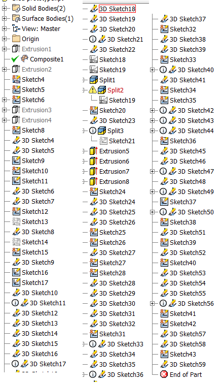
For those of you not using 2014 - here is the current browser history tree for the part.
(I think we can simplify this a bit.)
(see attached - put your coffee down first ![]() )
)
I will be back in a little while with a simplified part.
-----------------------------------------------------------------------------------------
Autodesk Inventor 2019 Certified Professional
Autodesk AutoCAD 2013 Certified Professional
Certified SolidWorks Professional
Message 12 of 15
07-08-2013
02:59 PM
- Mark as New
- Bookmark
- Subscribe
- Mute
- Subscribe to RSS Feed
- Permalink
- Report
07-08-2013
02:59 PM
It was really difficutl to determine your design intent from your model construction, but if this doesn't help - post back.
(see attached file)
-----------------------------------------------------------------------------------------
Autodesk Inventor 2019 Certified Professional
Autodesk AutoCAD 2013 Certified Professional
Certified SolidWorks Professional
Message 14 of 15
07-09-2013
12:20 PM
- Mark as New
- Bookmark
- Subscribe
- Mute
- Subscribe to RSS Feed
- Permalink
- Report
07-09-2013
12:20 PM
File>New *.idw
I recommend that you go through the Help>Learning Tools>Tutorials and Skilbuilders.
-----------------------------------------------------------------------------------------
Autodesk Inventor 2019 Certified Professional
Autodesk AutoCAD 2013 Certified Professional
Certified SolidWorks Professional
Message 15 of 15
07-09-2013
01:31 PM
- Mark as New
- Bookmark
- Subscribe
- Mute
- Subscribe to RSS Feed
- Permalink
- Report
07-09-2013
01:31 PM
It occurred to me that you might not know how to edit an existing part.
Drag the red End of Part marker to just below ExtrusionSrf1.
Click on the + symbol next to ExtrusionSrf1.
Right click on Sketch1 and select Edit.
Examine
Finish sketch and pull down the red EOP to just below Trim1.
Repeat above steps examine the next sketch.
Step-by-step you can examine how the geometry was created and edit as needed.
See attached image.
-----------------------------------------------------------------------------------------
Autodesk Inventor 2019 Certified Professional
Autodesk AutoCAD 2013 Certified Professional
Certified SolidWorks Professional
Reply
Topic Options
- Subscribe to RSS Feed
- Mark Topic as New
- Mark Topic as Read
- Float this Topic for Current User
- Bookmark
- Subscribe
- Printer Friendly Page
Forums Links
Can't find what you're looking for? Ask the community or share your knowledge.
Post to forums
