Community
- Forums Home
- >
- Inventor Community
- >
- Inventor Forum
- >
- Re: Create a Circular Component Pattern, and maintain Orientation
Inventor Forum
Welcome to Autodesk’s Inventor Forums. Share your knowledge, ask questions, and explore popular Inventor topics.
Turn on suggestions
Auto-suggest helps you quickly narrow down your search results by suggesting possible matches as you type.
Reply
Topic Options
- Subscribe to RSS Feed
- Mark Topic as New
- Mark Topic as Read
- Float this Topic for Current User
- Bookmark
- Subscribe
- Printer Friendly Page
Message 1 of 9
Anonymous
2378 Views, 8 Replies
10-04-2012
11:10 AM
- Mark as New
- Bookmark
- Subscribe
- Mute
- Subscribe to RSS Feed
- Permalink
- Report
10-04-2012
11:10 AM
Create a Circular Component Pattern, and maintain Orientation
Hi All,
I was wondering if anyone can help my create a circular pattern in an assembly that maintains the orientation of the part being patterned.
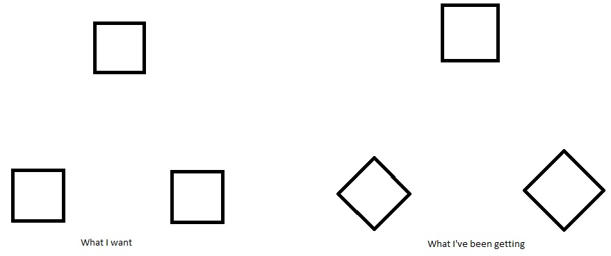
This is for foundation plates. There are 3 plates. The plates are square, and have bolt holes in the corners of the plates. Since there are 3 plates and its going around a circle, the angle between the plates is 120 degrees.
Now, Ive been trying this for some time now and what is happening is the firs plate is fine, but then the second and third plate are rotated around their center axis. I would like it to simply remain as inserted and constrained within the assembly.
I have attached a picture to be more clear about what I want and what I'm currently getting.
Maybe someone knows more about this and can possibly help me out with this.
I would really appreciate this.
Cheers,
---
Vijai Christopher Sookrah
Mechanical Engineer, EIT
Aircraft Appliances & Equipment Ltd.
8 REPLIES 8
Message 2 of 9
10-04-2012
11:24 AM
- Mark as New
- Bookmark
- Subscribe
- Mute
- Subscribe to RSS Feed
- Permalink
- Report
10-04-2012
11:24 AM
Me personally would not pattern 3 parts..
But to answer you issue there is no way to control the part from rotating with circular pattern.
Message 3 of 9
10-04-2012
11:27 AM
- Mark as New
- Bookmark
- Subscribe
- Mute
- Subscribe to RSS Feed
- Permalink
- Report
10-04-2012
11:27 AM
The reason why I try to pattern 3 parts is because we are trying to streamline this with an iassembly.
Ive already got the 4 plates case in properly.
to be completely honest I was hoping this would work just so there was no need to manually add parts.
I cant believe there is no option for this.
Thanks though
Message 5 of 9
10-04-2012
12:16 PM
- Mark as New
- Bookmark
- Subscribe
- Mute
- Subscribe to RSS Feed
- Permalink
- Report
10-04-2012
12:16 PM
I dont really understand why Inventor has such little functionality in this area and many more.
I found a work around which I thought would save the day but then I woke up and smelt the coffee.
My idea was to make the components that were out of orientation independant and then re mate them accordingly with the geometry. This would have worked well because it would blend in well with my iassembly features, but for some reason these parts dont have any references when made independant. Not only do they have no axis, no planes or points; in assembly files you dont have the ability to create planes, points, or axis as freely as you do in part files.
For Shame, Autodesk. For Shame.
Message 6 of 9
10-04-2012
12:26 PM
- Mark as New
- Bookmark
- Subscribe
- Mute
- Subscribe to RSS Feed
- Permalink
- Report
10-04-2012
12:26 PM
LOL thats funny that would have been my thought but I knew that making them independant would just be a part.
Message 7 of 9
10-04-2012
02:13 PM
- Mark as New
- Bookmark
- Subscribe
- Mute
- Subscribe to RSS Feed
- Permalink
- Report
10-04-2012
02:13 PM
Use rectangular pattern instead. Sketch a 240° arc and use that for Direction 1; expand the dialog box (>>) and you have choices for orientation (I'm not on an Inventor computer now, so I can't give you the details or a screen shot).
Message 8 of 9
10-05-2012
08:19 AM
- Mark as New
- Bookmark
- Subscribe
- Mute
- Subscribe to RSS Feed
- Permalink
- Report
10-05-2012
08:19 AM
I may be wrong, but I do not know if this will work in an Assembly file or will this only work in a Part file.
Cheers,
---
Vijai Christopher Sookrah
Mechanical Engineer
Aircraft Appliances & Equipment Ltd.
Message 9 of 9
10-05-2012
08:24 AM
- Mark as New
- Bookmark
- Subscribe
- Mute
- Subscribe to RSS Feed
- Permalink
- Report
10-05-2012
08:24 AM
@Anonymous wrote:I may be wrong, but I do not know if this will work in an Assembly file or will this only work in a Part file.
Create pattern of workpoints (or other geometry) in part with this technique and then in assembly constrain using the part pattern feature.
-----------------------------------------------------------------------------------------
Autodesk Inventor 2019 Certified Professional
Autodesk AutoCAD 2013 Certified Professional
Certified SolidWorks Professional
Reply
Topic Options
- Subscribe to RSS Feed
- Mark Topic as New
- Mark Topic as Read
- Float this Topic for Current User
- Bookmark
- Subscribe
- Printer Friendly Page
