Community
- Forums Home
- >
- Inventor Community
- >
- Inventor Forum
- >
- Re: Associating Two Sketches In A Frame Generator Assembly
Inventor Forum
Welcome to Autodesk’s Inventor Forums. Share your knowledge, ask questions, and explore popular Inventor topics.
Turn on suggestions
Auto-suggest helps you quickly narrow down your search results by suggesting possible matches as you type.
Reply
Topic Options
- Subscribe to RSS Feed
- Mark Topic as New
- Mark Topic as Read
- Float this Topic for Current User
- Bookmark
- Subscribe
- Printer Friendly Page
Message 1 of 11
09-04-2011
08:49 PM
- Mark as New
- Bookmark
- Subscribe
- Mute
- Subscribe to RSS Feed
- Permalink
- Report
09-04-2011
08:49 PM
Associating Two Sketches In A Frame Generator Assembly
I have sketches that are used in framed shower door assemblies and I am trying to use the main sketch as the outside perimeter w/ associated parts while the door is separate so it can pivot independently from the rest of the assembly. My question is: How do I associate the door sketch to change size when the door opening changes size in the main sketch?
Steve Frey
Inventor 2021
Windows 10 Professional 64-bit
HP ZBook 17 G6
Processor: Intel(R) Core(TM) i9-9880H CPU @ 2.30GHz
Memory: 80 GB
NVIDIA Quadro RTX5000
3D Connexion SpaceMouse Wireless
Inventor 2021
Windows 10 Professional 64-bit
HP ZBook 17 G6
Processor: Intel(R) Core(TM) i9-9880H CPU @ 2.30GHz
Memory: 80 GB
NVIDIA Quadro RTX5000
3D Connexion SpaceMouse Wireless
10 REPLIES 10
Message 2 of 11
09-05-2011
06:35 AM
- Mark as New
- Bookmark
- Subscribe
- Mute
- Subscribe to RSS Feed
- Permalink
- Report
09-05-2011
06:35 AM
Hi Steve,
For now, Inventor doesn't have such functionality to associate geometries between two sketches. We've already taken this into consideration and try to make this in the future. Thank you very much for pointing out your questions.
Best Regards,
Debbie
Debbie Lou
Sr. QA Engineer for HSM CAM
Message 3 of 11
09-05-2011
09:02 AM
- Mark as New
- Bookmark
- Subscribe
- Mute
- Subscribe to RSS Feed
- Permalink
- Report
09-05-2011
09:02 AM
Thanks Debbie. What about using a dummy parameter file to drive the sizes?
Steve Frey
Inventor 2021
Windows 10 Professional 64-bit
HP ZBook 17 G6
Processor: Intel(R) Core(TM) i9-9880H CPU @ 2.30GHz
Memory: 80 GB
NVIDIA Quadro RTX5000
3D Connexion SpaceMouse Wireless
Inventor 2021
Windows 10 Professional 64-bit
HP ZBook 17 G6
Processor: Intel(R) Core(TM) i9-9880H CPU @ 2.30GHz
Memory: 80 GB
NVIDIA Quadro RTX5000
3D Connexion SpaceMouse Wireless
Message 4 of 11
09-05-2011
09:58 AM
- Mark as New
- Bookmark
- Subscribe
- Mute
- Subscribe to RSS Feed
- Permalink
- Report
09-05-2011
09:58 AM
Attached is a quick example of what I understand you are asking for
May well be wrong in my understanding, though
Adjusting either of the two parameters in the FrameSketch will propagate to the door part
PDSU 2016
Message 5 of 11
09-05-2011
06:17 PM
- Mark as New
- Bookmark
- Subscribe
- Mute
- Subscribe to RSS Feed
- Permalink
- Report
09-05-2011
06:17 PM
Looks like you understand what I'm trying to do. So from what you created I would open the Door&FrameTemp.iam and control it from the FrameSketch.ipt. Now I just need to understand how you linked the two successfully. It's been a while since I tried it. I'll give it a try and let you know how I make out. Thanks!
Steve Frey
Inventor 2021
Windows 10 Professional 64-bit
HP ZBook 17 G6
Processor: Intel(R) Core(TM) i9-9880H CPU @ 2.30GHz
Memory: 80 GB
NVIDIA Quadro RTX5000
3D Connexion SpaceMouse Wireless
Inventor 2021
Windows 10 Professional 64-bit
HP ZBook 17 G6
Processor: Intel(R) Core(TM) i9-9880H CPU @ 2.30GHz
Memory: 80 GB
NVIDIA Quadro RTX5000
3D Connexion SpaceMouse Wireless
Message 6 of 11
09-05-2011
06:54 PM
- Mark as New
- Bookmark
- Subscribe
- Mute
- Subscribe to RSS Feed
- Permalink
- Report
09-05-2011
06:54 PM
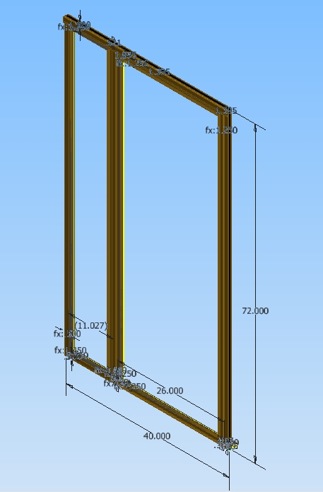
Okay, now that I'm thinking about this the model you sent to me is simple enough to do without associating the frames. Where it starts to be more complicated is when there's a door with at least one fixed panel like in the attached image. Now the door size (26") will drive the panel size (11.027") or if I change the overall width (40") the door stays the same but the fixed panel changes accordingly. I've done this in the SK (attached) but like I said I need the door to swing open in the assembly as a representation.
Steve Frey
Inventor 2021
Windows 10 Professional 64-bit
HP ZBook 17 G6
Processor: Intel(R) Core(TM) i9-9880H CPU @ 2.30GHz
Memory: 80 GB
NVIDIA Quadro RTX5000
3D Connexion SpaceMouse Wireless
Inventor 2021
Windows 10 Professional 64-bit
HP ZBook 17 G6
Processor: Intel(R) Core(TM) i9-9880H CPU @ 2.30GHz
Memory: 80 GB
NVIDIA Quadro RTX5000
3D Connexion SpaceMouse Wireless
Message 8 of 11
09-06-2011
09:49 AM
- Mark as New
- Bookmark
- Subscribe
- Mute
- Subscribe to RSS Feed
- Permalink
- Report
09-06-2011
09:49 AM
That looks like it works. I guess I'm not understanding how to link the two frames together.
Steve Frey
Inventor 2021
Windows 10 Professional 64-bit
HP ZBook 17 G6
Processor: Intel(R) Core(TM) i9-9880H CPU @ 2.30GHz
Memory: 80 GB
NVIDIA Quadro RTX5000
3D Connexion SpaceMouse Wireless
Inventor 2021
Windows 10 Professional 64-bit
HP ZBook 17 G6
Processor: Intel(R) Core(TM) i9-9880H CPU @ 2.30GHz
Memory: 80 GB
NVIDIA Quadro RTX5000
3D Connexion SpaceMouse Wireless

Message 10 of 11
09-14-2011
08:30 PM
- Mark as New
- Bookmark
- Subscribe
- Mute
- Subscribe to RSS Feed
- Permalink
- Report
09-14-2011
08:30 PM
I tried to do this many times but I'm not able to link the parameters. Can you give me any pointers? Thanks.
Steve Frey
Inventor 2021
Windows 10 Professional 64-bit
HP ZBook 17 G6
Processor: Intel(R) Core(TM) i9-9880H CPU @ 2.30GHz
Memory: 80 GB
NVIDIA Quadro RTX5000
3D Connexion SpaceMouse Wireless
Inventor 2021
Windows 10 Professional 64-bit
HP ZBook 17 G6
Processor: Intel(R) Core(TM) i9-9880H CPU @ 2.30GHz
Memory: 80 GB
NVIDIA Quadro RTX5000
3D Connexion SpaceMouse Wireless
Reply
Topic Options
- Subscribe to RSS Feed
- Mark Topic as New
- Mark Topic as Read
- Float this Topic for Current User
- Bookmark
- Subscribe
- Printer Friendly Page
Forums Links
Can't find what you're looking for? Ask the community or share your knowledge.
Post to forums
