Baseplate with holding down bolts subject to Tension and Shear

Baseplate with holding down bolts subject to Tension and Shear

Anonymous
Not applicable
7,370 Views
8 Replies
Message 1 of 9

Baseplate with holding down bolts subject to Tension and Shear

Anonymous
Not applicable

Hello


I am trying to design a baseplate for a 203x203x46 UB column on a square baseplate subject to 726kN of ULS tension and 160kN of shear sat on a concrete foundation of grade C32/40. I cannot seem to find an arrangement that works and keep getting a concrete cone failure. The section of the calculation notes that relates to the cone capacity is carried out according to the "CEB Design Guide: Design of fastenings on concrete". I am unable to source a copy of this document to see what I need to change to make the baseplate work.


Any help would be appreciated? I have attached a copy of the robot file that contains the baseplate.

0 Likes
Accepted solutions (2)
7,371 Views
8 Replies
Replies (8)
Message 2 of 9

Artur.Kosakowski
Autodesk Support
Autodesk Support
Accepted solution

You need to decrease level arm (e.g. by reducing tg) or e.g. increase diameters of anchors.


The link to the reference book is:

http://www.icevirtuallibrary.com/content/book/100270


If you find your post answered press the Accept as Solution button please. This will help other users to find solutions much faster. Thank you.


Artur Kosakowski
0 Likes
Message 3 of 9

Anonymous
Not applicable

Artur


Thanks for the reply. I uploaded an old version of the file by mistake! In the meantime I have had some help from a colleague and have found a solution.

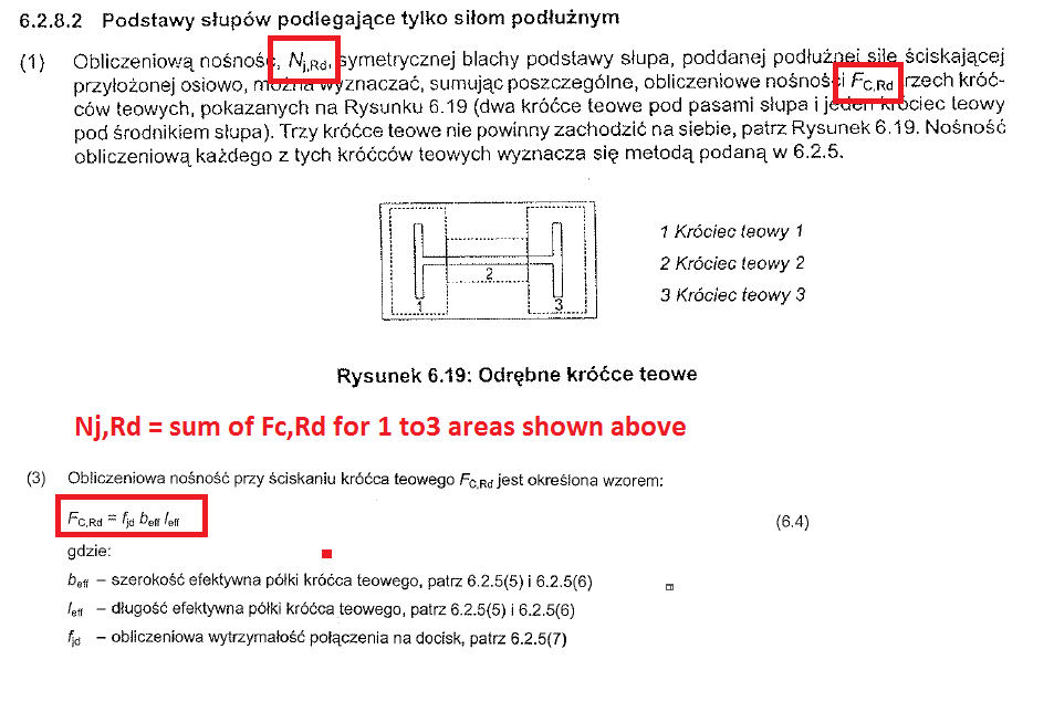
I am curious though as to how robot calculates Nj,Rd. It references 6.2.8.3 in BS EN 1993-1-8:2005 but having read it I can't see how Nj,Rd is calculated.


I have uploaded the final version of the design that works so you can use it in reference to a reply to my question.


Many thanks.

0 Likes
Message 4 of 9

Artur.Kosakowski
Autodesk Support
Autodesk Support
Accepted solution

NjRd.PNG


Artur Kosakowski
Message 5 of 9

Anonymous
Not applicable

Artur


That clause only seems to be relevant for compressive forces. In my example I have a tension load.

0 Likes
Message 6 of 9

Artur.Kosakowski
Autodesk Support
Autodesk Support

Mind the sign convention in the connection module.


http://docs.autodesk.com/RSA/2013/ENU/filesROBOT/GUID-3BBC4C06-F403-453A-A3C3-793916A5F64A.htm


sign convention.PNG


Artur Kosakowski
0 Likes
Message 7 of 9

Anonymous
Not applicable

I did notice that the sign convention calls for Tension loads to be entered as positive axial loads and I have entered that into my design a few posts above. As it is tension Nj,Rd is not the sum of FC,Rd for the 3 equivalent T-stubs in clause 6.2.5 as FC,Rd is a compressive resitance. 


If you open up the last model I posted you will see two designs, one for the maximum compression combination and one for the maximum tension combination. I cannot see in the calculation note how Nj,Rd is calcualted. Even in the compression case it does not appear to conform to the clasue you quoted above.


Sorry for the barrage of questions, I do not design many connections and this is the first time I have designed any to Eurocodes. I have spent some time looking at the code BS EN 1993-1-8 but do not find it easy to follow. Through all my searching on the interent I cannot find examples for tension loads on baseplates. Your help is appreciated.

0 Likes
Message 8 of 9

Artur.Kosakowski
Autodesk Support
Autodesk Support

I'm sorry for some reason I switched my attention from the first to the second of defined connection. For the under tension one:


tension in fixed column base.PNG


Artur Kosakowski
Message 9 of 9

Anonymous
Not applicable

Artur.


It seems obvious now you have pointed it out to me.Smiley LOL


Thankyou for your patience!


0 Likes