Community
- Forums Home
- >
- Inventor Community
- >
- Inventor Forum
- >
- This is retarded! Why is this a spline in IDW???
Inventor Forum
Welcome to Autodesk’s Inventor Forums. Share your knowledge, ask questions, and explore popular Inventor topics.
Turn on suggestions
Auto-suggest helps you quickly narrow down your search results by suggesting possible matches as you type.
Reply
Topic Options
- Subscribe to RSS Feed
- Mark Topic as New
- Mark Topic as Read
- Float this Topic for Current User
- Bookmark
- Subscribe
- Printer Friendly Page
Message 1 of 16
01-28-2011
08:19 PM
- Mark as New
- Bookmark
- Subscribe
- Mute
- Subscribe to RSS Feed
- Permalink
- Report
01-28-2011
08:19 PM
This is retarded! Why is this a spline in IDW???
Guys
Ok, I am new to Inventor. I get that.
What I don't get is why is the drawing of the attached part turns into a spline in the indicated area!
I understand that most of you guys do not have to deal or be concerned with garbage like this, but for us "blacksmiths"
this is just absolutely retarded and creates a whole bunch of extra work!
And while on the subject, is there any way ( or is there any work-in-progress to provide such a way ) to create a 2D drawing
from a part where the outline becomes a single entity geometry?
I mean if we are in 2D, we are actually "falttening" the 3D solid, which in theory should result in a continuous entity, broken only if there is a change in type or direction?
Please don't misunderstand, I'm beginning to like Inventor to do all my drawings. I've all but stopped re-creating the blueprint
provided to me in ACAD and pretty much draw everything in Inventor and then transfer the drawing into Autocad, but stuff like this makes the whole process almost not worth it!
Again, I'm not an engineering firm, I am a jobshop who needs a fair amount of 2D geometry to be used for various purposes. The way IV is working for this purpose is quite hostile at times.
Btw, this is Inventor 2011 Pro.
Thank you.
15 REPLIES 15
Message 2 of 16
01-29-2011
02:14 AM
- Mark as New
- Bookmark
- Subscribe
- Mute
- Subscribe to RSS Feed
- Permalink
- Report
01-29-2011
02:14 AM
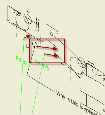
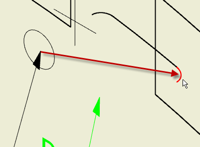
Much of the functionality of Inventor drawings comes from the fact that the drawings are in fact not 2D. If you rotate your drawing sheet, you will see that the drawing views are actually 3D geometry extracted from the model (see IDW_Spline1.png). The other two images zoom in on the edge of interest. You can see the same thing if you create a sketch on the front face of the part (model) and try to project that edge into the sketch. Inventor blocks this as well.
It would be nice if they had an option to convert these projections into the aprropriate arc (if within a certain tolerance perhaps).

Message 4 of 16
01-29-2011
05:09 AM
- Mark as New
- Bookmark
- Subscribe
- Mute
- Subscribe to RSS Feed
- Permalink
- Report
Message 5 of 16
01-29-2011
06:58 AM
- Mark as New
- Bookmark
- Subscribe
- Mute
- Subscribe to RSS Feed
- Permalink
- Report
01-29-2011
06:58 AM
Because this fillet becomes a spline in your view.

Use leader text or dimension a fillet in a different view:

In a machining operation, this should have no effect, as you would generally cut the the outer profile (arc) first, then mill the pocket. What CAM software are you usiing? Most CAM systems have algorithms to interpolate and "meld" the spline into the toolpath.
Please mark this response as "Accept as Solution" if it answers your question.
____________________________________________________________
Dennis Jeffrey, Author and Manufacturing Trainer, Autodesk Inventor Certified Expert
Autodesk Manufacturing Implementation Certified Expert
Autodesk Silver Manufacturing Partner
Subscribe to the free digital "The Creative Inventor Magazine" now available at: http://teknigroup....
XP64 SP2, GeForce 9800GT-1GB, Driver: 6.14.12.7061, 8GB Ram, AMD Athlon II 3.2 Ghz
Laptop: Win7-64 Pro, 4GB, ATI Graphics on board, 2012 Ultimate, IV2011 or 2010 Pro, all SP's
Message 6 of 16
01-29-2011
10:24 AM
- Mark as New
- Bookmark
- Subscribe
- Mute
- Subscribe to RSS Feed
- Permalink
- Report
01-29-2011
10:24 AM
Dennis
That's just it!
Why does the fillet become a spline??? In the top view, that fillet does in fact reside in a continuous path and it is in fact an arc! There is no possible way of explaining it any other way! That fillet still follows the contour of the underlying arc and it should show as such.
I use Featurecam for mill programming and it can use the solid as the base, and it DOES IN FACT!!! create a single entity of the outline when I ask it to project the vertical edges. Isn't it odd that a CAM program does that but the modeling tool itself does not?
As far as the spline-fitting comment, you should look at how some of the so called "industry standard" CAM programs handle splines! They break it into .001-.002 long individual line segments, which results in a 100 line code just to make a 1/4" movement! At least Featurecam gives the option to use tangent arcs instead, but MC for example does not, neither does Gibbs.
I still do not understand this tough. The outline was created as a single 2D arc in the first sketch. So why then does the IDW environment still uses a broken up edge????
The rotation of the IDW is a cool thing, but IMO makes no sense at all. First off, if it's 2D then it should have no depth.
Second, I know it isn't the cause as the entities still all have a Z value of 0 when transferred into AutoCAD.
Not trying to start a war of words here, but wouldn't it be nice if IV offered an option of "squash", "mold", "flatten", "combine" or call it whatever you want to create a true 2D representation of the solid model?
I know it does not make a hill of beans on todays printers or plotters, but imagine if you're a signmaker and you knife is dancing a jig for a portion of your profile? What if your wire EDM is jiggling around with tiny line segments on cutting a cam? Your endmill with a left or right cutter comp trying to make small line segments which it cannot actually make?
To Autodesk, please understand that there are not only engineers who use your software! It is also used in the manufacturing environment to drive cutting tools and the way things work now is making that wicked painful!
Message 7 of 16
01-29-2011
11:08 AM
- Mark as New
- Bookmark
- Subscribe
- Mute
- Subscribe to RSS Feed
- Permalink
- Report
01-29-2011
11:08 AM
I do understand your frustration, but in the end, it's an area for CAM. Your original post seemed to indicate your frustration with not being able to annotate that spline which in fact wa an object created bt projecting the fillet radius into the 2D view.
Thankfully the CAM packages today typically generate toolpaths from the model, not the drawings. In that light, this may be a moot point.
Please mark this response as "Accept as Solution" if it answers your question.
____________________________________________________________
Dennis Jeffrey, Author and Manufacturing Trainer, Autodesk Inventor Certified Expert
Autodesk Manufacturing Implementation Certified Expert
Autodesk Silver Manufacturing Partner
Subscribe to the free digital "The Creative Inventor Magazine" now available at: http://teknigroup....
XP64 SP2, GeForce 9800GT-1GB, Driver: 6.14.12.7061, 8GB Ram, AMD Athlon II 3.2 Ghz
Laptop: Win7-64 Pro, 4GB, ATI Graphics on board, 2012 Ultimate, IV2011 or 2010 Pro, all SP's
____________________________________________________________
Dennis Jeffrey, Author and Manufacturing Trainer, Autodesk Inventor Certified Expert
Autodesk Manufacturing Implementation Certified Expert
Autodesk Silver Manufacturing Partner
Subscribe to the free digital "The Creative Inventor Magazine" now available at: http://teknigroup....
XP64 SP2, GeForce 9800GT-1GB, Driver: 6.14.12.7061, 8GB Ram, AMD Athlon II 3.2 Ghz
Laptop: Win7-64 Pro, 4GB, ATI Graphics on board, 2012 Ultimate, IV2011 or 2010 Pro, all SP's
Message 8 of 16
01-29-2011
11:10 AM
- Mark as New
- Bookmark
- Subscribe
- Mute
- Subscribe to RSS Feed
- Permalink
- Report
01-29-2011
11:10 AM
Rotate IDW with 3D motion controller, it requires un-locking the rotate command for IDW's. It's easier on the more expensive models with more buttons have the basic controller.
Inventor 2020, In-Cad, Simulation Mechanical
Just insert the picture rather than attaching it as a file
Did you find this reply helpful ? If so please use the Accept as Solution or Kudos button below.
Delta Tau Chi ΔΤΧ
Message 10 of 16
01-29-2011
03:49 PM
- Mark as New
- Bookmark
- Subscribe
- Mute
- Subscribe to RSS Feed
- Permalink
- Report
01-29-2011
03:49 PM
""""
Your original post seemed to indicate your frustration with not being able to annotate that spline which in fact wa an object created bt projecting the fillet radius into the 2D view.
Thankfully the CAM packages today typically generate toolpaths from the model, not the drawings. In that light, this may be a moot point.
""""
Dennis
In the intial post I was just using the annotation to show that the outline - which should be a single 2D enity - is actually broken into multiple arcs with one area actually being a spline. Someone please tell me how is that correct!
Attached there is another DWG file. This was created by taking the above posted IPT, save it as STEP. Import into SOlidworks2007, then created a drawing from it, which was then saved as AutoCAD DWG.
Please note that the result in the area in question is in fact a true arc!!!
Solidworks still does the braking up of the outline into individual elements just as Inventor, but it also recognizes that there is no spline anywhere!
So which software is correct?
As far as CAM being able to work with solids, that is true.
What is also true that many modern CNC machinetools allow the importing of DXF or even AutoCAD DWG directly and does the programming right on the control. Depending on your requirement, this may be a very valuable tool and people often choose to pay a pretty hefty price for the option. No matter what control you have tough, if the imported DXF contains multiple continuous entities, it will cut it as multiple entity which often results in an ever so slight line at the intersections.
Moreover, if the imported DXF contains a spline it will be cut using a boatload of individual miniscule line segments.
Should that be so just because Inventor does not recognize an entity for what it is?
Please, someone tell why am I wrong and I'll shut up.
Message 11 of 16
01-29-2011
04:46 PM
- Mark as New
- Bookmark
- Subscribe
- Mute
- Subscribe to RSS Feed
- Permalink
- Report
01-29-2011
04:46 PM
You're not wrong, maybe still a bit confused but nothing wrong with that (I'm often in that state).
You missed the intention of my first reply, it was not to show that the sheet could be rotated, but to show that an Inventor drawing is not 2D. Each view is portions of the 3D model shown from a fixed parallel viewpoint to give the appearance of a 2D drawing view. The arc that reports as a spline is a true arc but the arc is not parallel to the view and would therefore need to be projected into the plane of the view to be dimensioned. I agree with you that Inventor should be able to interpret these projections as arcs as other SW seems to be able to do. When you export an Inventor drawing to AutoCAD, the flattening of objects takes place during the translation.
I know this doesn't solve anything, just hope it helps a bit with understanding what is happening.
(I used a two line macro to rotate the view of the sheet)
Message 12 of 16
01-29-2011
06:11 PM
- Mark as New
- Bookmark
- Subscribe
- Mute
- Subscribe to RSS Feed
- Permalink
- Report
01-29-2011
06:11 PM
Now isn't that interesting!
Just did nmunro's suggestion and hit ISO on the Navigator.
Apparently, Inventor is smart to know and recognize geometry that is overlaying another, and shows visible entities only once. Odd enough that it keeps them on it's own Z-level in 3D space, yet considers it as 2D when viewed from atop.
IOW if I try to click the radius on the bottom of the cutout, that entity actually lies in a 3D plane.
Wonder just what is the reasoning behind it really???
I did try to ( just for giggles ) create a Z-depth dimension from the top face and the bottom of the slot in the ISO view, it does
not do it.
So what possible useful purpose is there for this?
Message 13 of 16
01-31-2011
08:20 AM
- Mark as New
- Bookmark
- Subscribe
- Mute
- Subscribe to RSS Feed
- Permalink
- Report
01-31-2011
08:20 AM
A number of releases ago, Autodesk made major improvements in IDW speed. Possibly this is where they introduced this.
Inventor 2020, In-Cad, Simulation Mechanical
Just insert the picture rather than attaching it as a file
Did you find this reply helpful ? If so please use the Accept as Solution or Kudos button below.
Delta Tau Chi ΔΤΧ
Message 14 of 16
01-31-2011
06:19 PM
- Mark as New
- Bookmark
- Subscribe
- Mute
- Subscribe to RSS Feed
- Permalink
- Report
01-31-2011
06:19 PM
Ok, so here is another question:
Would I be way out of line to ask that this issue be added to the wishlist to fix?
I mean I somehow get the feeling from most here that this is a "so what", no big deal.
If yes, then where would it be best to add?
Thank You
Message 15 of 16
01-31-2011
06:52 PM
- Mark as New
- Bookmark
- Subscribe
- Mute
- Subscribe to RSS Feed
- Permalink
- Report
01-31-2011
06:52 PM
@acad-caveman wrote:Ok, so here is another question:
Would I be way out of line to ask that this issue be added to the wishlist to fix?
I mean I somehow get the feeling from most here that this is a "so what", no big deal.
If yes, then where would it be best to add?
You can make your request at the link I've listed below. I would suggest that when doing so, you refrain from using words that might be considered demeaning to people with special needs. That's probably a good thing to consider in general, as it reflects poorly on you, and is offensive to people who have mental challenges or know and care for people who do.
http://usa.autodesk.com/adsk/servlet/index?siteID=123112&id=1109794
Message 16 of 16
01-31-2011
07:45 PM
- Mark as New
- Bookmark
- Subscribe
- Mute
- Subscribe to RSS Feed
- Permalink
- Report
01-31-2011
07:45 PM
Not much a P.C. fan, but point taken and will keep in mind.
Thank you for the link.
Reply
Topic Options
- Subscribe to RSS Feed
- Mark Topic as New
- Mark Topic as Read
- Float this Topic for Current User
- Bookmark
- Subscribe
- Printer Friendly Page
