Community
AutoCAD Plant 3D Forum
Welcome to Autodesk’s AutoCAD Plant 3D Forums. Share your knowledge, ask questions, and explore popular AutoCAD Plant 3D topics.
Turn on suggestions
Auto-suggest helps you quickly narrow down your search results by suggesting possible matches as you type.
Reply
Topic Options
- Subscribe to RSS Feed
- Mark Topic as New
- Mark Topic as Read
- Float this Topic for Current User
- Bookmark
- Subscribe
- Printer Friendly Page
Message 1 of 3
03-09-2012
08:07 AM
- Mark as New
- Bookmark
- Subscribe
- Mute
- Subscribe to RSS Feed
- Permalink
- Report
03-09-2012
08:07 AM
Pipe missing flanges in iso
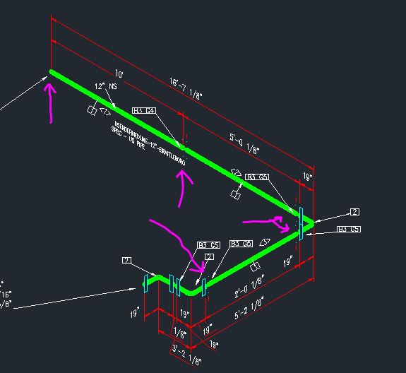
In my Iso drawings I have FLxFL pipe & fittings. The flanged ends of the fittings are showing up correctly but pipe is coming out with no flanges. See attached screen shot. From what I understand about the SKEY mapping file, the end connections drawn are based on the end connection codes (FL) of the part. My mapping files points FL to the FittingFlange block. Both my fitting and pipe use the FL code so shouldn't they both come out the same in iso... what am I missing? Thanks!
2 REPLIES 2
Message 2 of 3
03-09-2012
12:15 PM
- Mark as New
- Bookmark
- Subscribe
- Mute
- Subscribe to RSS Feed
- Permalink
- Report
03-09-2012
12:15 PM
You have to create your own symbol keys.
We have an article how to do that here:
http://www.pdoteam.com/2011/10/create-new-symbols-for-isometrics-in-autocad-plant-3d/
I ended up putting creating a PIFL key. You can't use the PIPE type because the isometric program just draws lines. You can use a different type like ELBOW.


Message 3 of 3
03-12-2012
11:08 AM
- Mark as New
- Bookmark
- Subscribe
- Mute
- Subscribe to RSS Feed
- Permalink
- Report
03-12-2012
11:08 AM
Dave, Thanks (again!) for your reply.
Let me make sure I have this straight: When the system sees an Iso Symbol Type of PIPE it ignores the end types and doesn't use the mapped connection symbols. So in the catalog/specs for flanged pipe you change the Iso Symbol Type to something else, say ELBOW. Then you add an SKEY that maps to a symbol that is a straight line (to represent the pipe). Because the Iso Symbol Type is not PIPE it looks for the end types and applies the appropriate symbols?
I've seen no documentation for Iso Symbol Types... Is there a list out there. Or a file or dialog box that defines them?
Thanks! -Jason
Reply
Topic Options
- Subscribe to RSS Feed
- Mark Topic as New
- Mark Topic as Read
- Float this Topic for Current User
- Bookmark
- Subscribe
- Printer Friendly Page

