Community
- Forums Home
- >
- AutoCAD Plant 3D Community
- >
- AutoCAD Plant 3D Forum
- >
- Re: P3D 2012: ISO setting problems
AutoCAD Plant 3D Forum
Welcome to Autodesk’s AutoCAD Plant 3D Forums. Share your knowledge, ask questions, and explore popular AutoCAD Plant 3D topics.
Turn on suggestions
Auto-suggest helps you quickly narrow down your search results by suggesting possible matches as you type.
Reply
Topic Options
- Subscribe to RSS Feed
- Mark Topic as New
- Mark Topic as Read
- Float this Topic for Current User
- Bookmark
- Subscribe
- Printer Friendly Page
Message 1 of 15
08-31-2011
11:10 AM
- Mark as New
- Bookmark
- Subscribe
- Mute
- Subscribe to RSS Feed
- Permalink
- Report
08-31-2011
11:10 AM
I have ran into a few more ISO setting problems:
- no matter what I set the valve dimensioning setting to "end to end" or to "center" it dimensions to center of valve
- directional valves (such as check valves) orientaion sometime will point to the opposite direction, this happens sometimes.
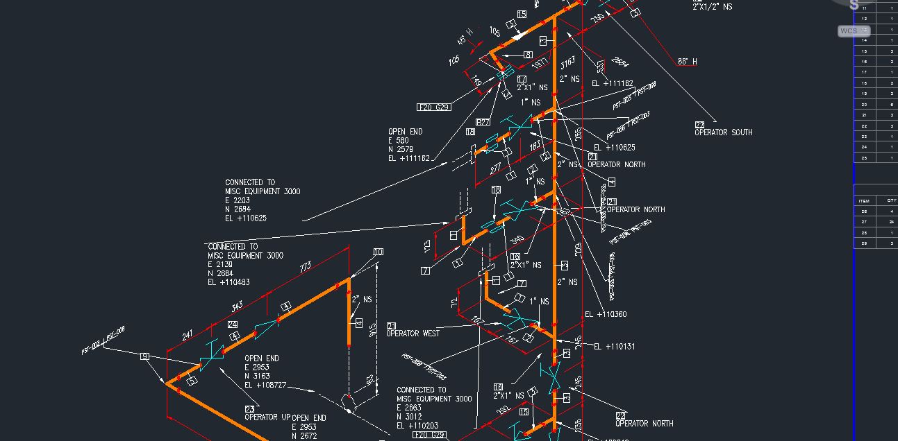
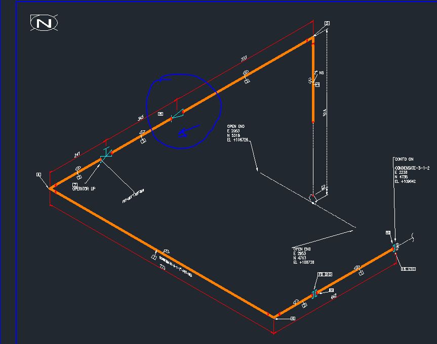
I can generate the same line same area 5 times and that same check valve will be facing the wrong direction 2 times out of 5. I have attached 2 screen shots of the same line, same area, did not change any settings.. just simply hit generate iso twice, and this is my results... the check valve's direction is different on the two.
I really think P3D 2012 is nothing but trouble. we are not just talking about cosmatic issues now... this is accuracy issues we have.
Solved! Go to Solution.
Solved by pkw167. Go to Solution.
Solved by ratti. Go to Solution.
Solved by murali.p. Go to Solution.
14 REPLIES 14
Message 2 of 15
08-31-2011
11:23 AM
- Mark as New
- Bookmark
- Subscribe
- Mute
- Subscribe to RSS Feed
- Permalink
- Report
08-31-2011
11:23 AM
again, everytime I need to add to the message, the edit function never works for this forum, the only way to add to my message is to make another post.
so besides the dimension to end or center of valve function doesn't work, the option to include gaskets in the fitting dimension or to dimension gaskets individually also doesn't work... I have it set on include gaskets thickness in fitting, and has never changed it once. BUT it ALWAYS dimensions gaskets individually.
Message 3 of 15
09-04-2011
07:33 PM
- Mark as New
- Bookmark
- Subscribe
- Mute
- Subscribe to RSS Feed
- Permalink
- Report
09-04-2011
07:33 PM
For the 1st dimesion stop at valve issue, make sure uncheck below option: In Small Bore Piping Iso theme, Dimensioning behavior grid, uncheck Valves option. Could you verify it again and let me know the result?
For the 2nd Check valve direction, could you please post the PCF and let us to investigate?

Vicky
Autodesk Plant Solutions
Autodesk Plant Solutions
Message 4 of 15
09-04-2011
07:43 PM
- Mark as New
- Bookmark
- Subscribe
- Mute
- Subscribe to RSS Feed
- Permalink
- Report
09-04-2011
07:43 PM
I tried from my side. Set Include in component dimension in gasket handling drop-down menu and got correct iso. Could you please post the PCF and corresponding iso style zip file and let me to retry?

Vicky
Autodesk Plant Solutions
Autodesk Plant Solutions
Message 5 of 15
09-04-2011
11:22 PM
- Mark as New
- Bookmark
- Subscribe
- Mute
- Subscribe to RSS Feed
- Permalink
- Report
09-04-2011
11:22 PM
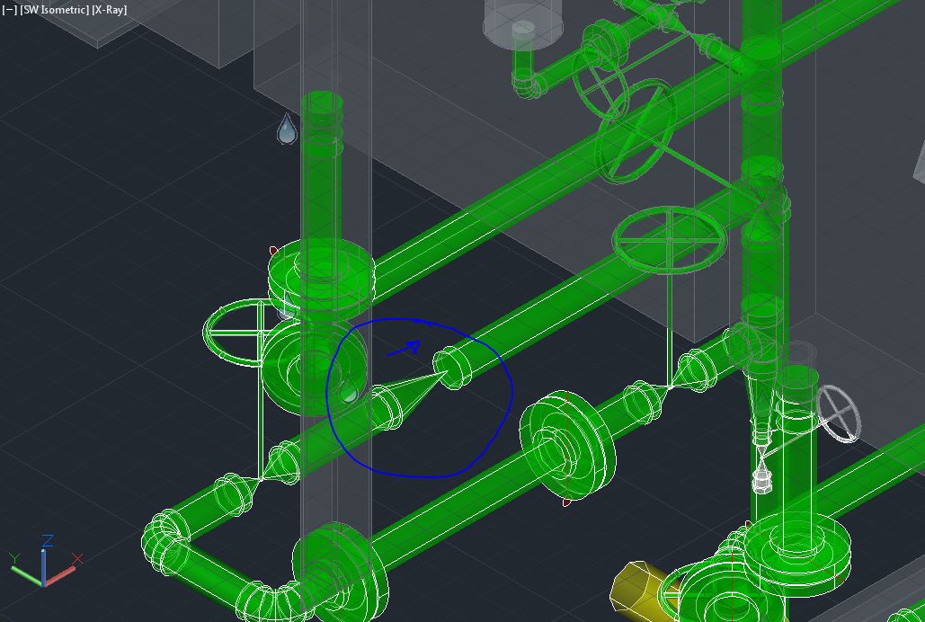
We could change check valve direction from Plant3D in the model via clicking the arrow. Is it possiable you click it carelessly before you create the same iso 2nd time?
Meanwhile, I noticed that there's a little difference between the 2 snapshot attached by you.
If we use the same iso style, we should always get same layout for same pipeline no matter how many times to create iso. So could you please double check it and post the PCF and iso style zip file to us?

Vicky
Autodesk Plant Solutions
Autodesk Plant Solutions
Message 6 of 15
09-05-2011
06:55 AM
- Mark as New
- Bookmark
- Subscribe
- Mute
- Subscribe to RSS Feed
- Permalink
- Report
09-05-2011
06:55 AM
"Meanwhile, I noticed that there's a little difference between the 2 snapshot attached by you."
yes... that's what I ment... it is very inconsistant. The two ISOs were actually generated one after another without changing any settings. Basically, I pressed Production ISO, select the line, and generate.. once the 1st ISO is generated, I press Production ISO again, selec the same line, no options are changed,and generate, like y ou mentioned, the two ISOs will look different, but that's not the big deal... its cosmetics, we have ISO cleanup people to look after that. BUT the valve direction IS a big deal. I have attached the PCF for this along with a screen shot of the line and area affected. My model shows the check valve going one way (W to E), but in my ISO, it is going (E to W).
(I have turned down the clutter this time to show the check valve more clearly).. but again, it's just cosmetics, it should not affect the direction of the valve.
which file is the iso style?
Thanks
Message 7 of 15
09-05-2011
08:59 PM
- Mark as New
- Bookmark
- Subscribe
- Mute
- Subscribe to RSS Feed
- Permalink
- Report
09-05-2011
08:59 PM
Hi,
I agree that the valve direction presented on the iso is a critical piece of information. We have looked into the issue and the PCF you have sent indicates that the check valve does not have the flow-aware attribute set. Without the flow direction information, the system has to make assumptions and thus flow direction cannot be guaranteed between the runs.
Was this PCF generated in Plant3D 2011? It looks likely as the flow attribute in PCF was not added automatically in Plant3D 2011. In Plant3D 2012 though, this attribute is added in the PCF for all out-of-the box check valves. If you are adding you own content, please set the attribute "Flow Dependent" to true.
Also you can set the specific direction on the check valve using Plant3D UI (as described in detail by Vicky Wu in her post above). Please try setting the check valve direction and generate the iso's again. That should fix the problem.
I have modified your PCF by adding the attribute to the check valve. Try this PCF and let us know if you still see the problem.
Regards,
Murali
Message 8 of 15
09-06-2011
06:01 AM
- Mark as New
- Bookmark
- Subscribe
- Mute
- Subscribe to RSS Feed
- Permalink
- Report
09-06-2011
06:01 AM
Thank you murali, the model and pcf was generated with P3D 2012, but i will look into the attribute setting as you indicated. As well, your modified PCF works well.
Thanks again.
Message 9 of 15
09-06-2011
04:55 PM
- Mark as New
- Bookmark
- Subscribe
- Mute
- Subscribe to RSS Feed
- Permalink
- Report
09-06-2011
04:55 PM
Hi,
Could you also please check whether the "FlowDependent" property for Check Valves is set to "True" or not?
That property is used to determine if the component has a flow direction associated with it or not.
If it is not set to "True", please set it to "True" and give it a try. However, if it is in fact set to "True", there are deeper issues. Could you please share your model in that case?
Thanks.
Ratti.
Autodesk, Inc.
Message 10 of 15
09-07-2011
06:35 AM
- Mark as New
- Bookmark
- Subscribe
- Mute
- Subscribe to RSS Feed
- Permalink
- Report
09-07-2011
06:35 AM
thanks for all the replies, I did check and noticed that the flow dependent was not set to true, so I when into spec editor and changed that back to true... how it default to not true is beyond me. But from now on, it will be something I double check when ever I am inserting a flow dependent component into my specs.
thanks again
Message 11 of 15
09-08-2011
12:31 AM
- Mark as New
- Bookmark
- Subscribe
- Mute
- Subscribe to RSS Feed
- Permalink
- Report
09-08-2011
12:31 AM
Hi
Similar to this, I am having a problem configuring the ISO settings to refer to specific piping items.
Example: I have flexible hose couplings inside my spec, in the previous ISO settings, in the Spec Editor, I put the iso info as follows:
ISO TYPE: MISC-COMPONENT
ISO SKEY: FXSW
How do I go about mapping the new symbols to these existing items?
Or how would I choose a specific block to be placed when the ISO TYPE and SKEY are as what I have mentioned above?
Thanks!
Message 12 of 15
09-08-2011
12:39 AM
- Mark as New
- Bookmark
- Subscribe
- Mute
- Subscribe to RSS Feed
- Permalink
- Report
09-08-2011
12:39 AM
Title block & display page in Project Setup, Click Edit isometric Symbols... to create a symbol and name it. remember to add ports for hose connector.
Go to install folder: \AutoCAD Plant 3D 2012 - English\ISOProjectTemplates
Open IsoSkeyACADBlockMap.xml, add your skey and block name into it.
Create Iso.
Vicky
Autodesk Plant Solutions
Autodesk Plant Solutions
Message 14 of 15
09-08-2011
08:26 AM
- Mark as New
- Bookmark
- Subscribe
- Mute
- Subscribe to RSS Feed
- Permalink
- Report
09-08-2011
08:26 AM
Hi,
One small addition.
Please edit the IsoSkeyACADBlockMap.xml file in the project that you are going to add the new isometric symbols.
That is, open IsoSkeyACADBlockMap.xm in say C:\Users\<username>\Documents\MyNewProject\Isometric, and add your skey and block name in that file.
You can also update the files (the IsoSymbolStyles.dwg and the IsoSkeyACADBlockMap.xml) in the install folder (\AutoCAD Plant 3D 2012 - English\ISOProjectTemplates) if you want *every* new project, in the given unit system, created from there on to have the new symbols and skeys.
If you want only the current working project to have the new skey support, please update only the project files.
HTH.
Ratti.
Autodesk, Inc.
Message 15 of 15
09-08-2011
05:28 PM
- Mark as New
- Bookmark
- Subscribe
- Mute
- Subscribe to RSS Feed
- Permalink
- Report
09-08-2011
05:28 PM
Ratti is correct. Try to modify all the files in project folder not install folder.
Vicky
Autodesk Plant Solutions
Autodesk Plant Solutions
Reply
Topic Options
- Subscribe to RSS Feed
- Mark Topic as New
- Mark Topic as Read
- Float this Topic for Current User
- Bookmark
- Subscribe
- Printer Friendly Page

