Community
AutoCAD Plant 3D Forum
Welcome to Autodesk’s AutoCAD Plant 3D Forums. Share your knowledge, ask questions, and explore popular AutoCAD Plant 3D topics.
Turn on suggestions
Auto-suggest helps you quickly narrow down your search results by suggesting possible matches as you type.
Reply
Topic Options
- Subscribe to RSS Feed
- Mark Topic as New
- Mark Topic as Read
- Float this Topic for Current User
- Bookmark
- Subscribe
- Printer Friendly Page
Message 1 of 17
04-24-2012
01:54 PM
- Mark as New
- Bookmark
- Subscribe
- Mute
- Subscribe to RSS Feed
- Permalink
- Report
04-24-2012
01:54 PM
Modeling up custom fittings
I am trying to figure out the easiest way create a saddle ( for sch 40 pvc )
I have it modeled up, converted to a block. the first time I made it into basically a Tee with 3 connection ports (with plantpartconvert ) two horizontal with 0 spacing and the reduction connection port vertically - like a Tee
but when I place it, it cuts the pipe in the center, which I would like to avoid.
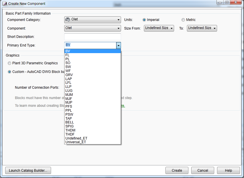
it would be basically an Olet but wrapping directly around the pipe. When creating a block based component
how many ports should an Olet have? and what would the behaviour be attaching to a pipe length?
I've never had any luck using the plant 3d parametric graphics, and I have all the fittings already modeled from when I didn't have P3D.
Just looking for a different perspective on this.
An education isn't how much you have committed to memory, or even how much you know. It's being able to differentiate between what you know and what you don't.
-------------------------------------
"Do or do not... there is no try"
Master Yoda.
16 REPLIES 16
Message 2 of 17
04-26-2012
03:26 PM
- Mark as New
- Bookmark
- Subscribe
- Mute
- Subscribe to RSS Feed
- Permalink
- Report
04-26-2012
03:26 PM
Hi John,
Are you using AutoCAD Plant 3D 2012 or 2013?
Also, are you needing a pipe saddle or a reinforcement pad?
2012 does not support pipe saddles/reinforcement pads (although there might be a way to use a modified olet to place it on a line)
2013 supports reinforcement pads natively:
http://autocad.autodesk.com/?nd=plant2013newfeatures
Jason Drew
Designated Support Specialist
Message 3 of 17
04-26-2012
03:32 PM
- Mark as New
- Bookmark
- Subscribe
- Mute
- Subscribe to RSS Feed
- Permalink
- Report
04-26-2012
03:32 PM
Pipe saddle. As in an bolted on tee
An education isn't how much you have committed to memory, or even how much you know. It's being able to differentiate between what you know and what you don't.
-------------------------------------
"Do or do not... there is no try"
Master Yoda.
An education isn't how much you have committed to memory, or even how much you know. It's being able to differentiate between what you know and what you don't.
-------------------------------------
"Do or do not... there is no try"
Master Yoda.
Message 4 of 17
04-27-2012
12:13 PM
- Mark as New
- Bookmark
- Subscribe
- Mute
- Subscribe to RSS Feed
- Permalink
- Report
04-27-2012
12:13 PM
I see what you mean by reinforcement pad, but can I have that show up as a saddle in the BOM?
http://www.spearsmfg.com/prod_brochures/COS-2-0804_0610_web.pdf
Also using 2013 now.
An education isn't how much you have committed to memory, or even how much you know. It's being able to differentiate between what you know and what you don't.
-------------------------------------
"Do or do not... there is no try"
Master Yoda.
Message 5 of 17
04-27-2012
05:27 PM
- Mark as New
- Bookmark
- Subscribe
- Mute
- Subscribe to RSS Feed
- Permalink
- Report
04-27-2012
05:27 PM
Also - any Ideas why the catalog builder keeps telling me no excel? ( when it is installed )
An education isn't how much you have committed to memory, or even how much you know. It's being able to differentiate between what you know and what you don't.
-------------------------------------
"Do or do not... there is no try"
Master Yoda.
Message 6 of 17
05-04-2012
08:23 AM
- Mark as New
- Bookmark
- Subscribe
- Mute
- Subscribe to RSS Feed
- Permalink
- Report
05-04-2012
08:23 AM
Hi John,
I'm currently checking into this issue and will let you know what I find out.
Thank you,
Jason Drew
Designated Support Specialist
Message 7 of 17
05-10-2012
07:14 AM
- Mark as New
- Bookmark
- Subscribe
- Mute
- Subscribe to RSS Feed
- Permalink
- Report
05-10-2012
07:14 AM
My first recomendation would be to reinstall Microsoft Office and then see if Plant 3D finds it. I've never ran into an issue where Plant 3D doesn't detect that MS Office is installed.
What version of Office are you using? I believe Office 2003 - 2010 is supported, but I've never tried using older versions.
Thank you,
Jason Drew
Designated Support Specialist
Message 8 of 17
05-20-2012
12:56 PM
- Mark as New
- Bookmark
- Subscribe
- Mute
- Subscribe to RSS Feed
- Permalink
- Report
05-20-2012
12:56 PM
So to continue,
trying to make a pvc pipe saddle (eg. http://www.spearsmfg.com/prod_brochures/COS-2-0804_0610_web.pdf )
I am using the olet base parameter.
what does the <End Type> need to be for the main pipe run? and for the reduction side I am using PSW.
currently I am just using PSW for both and it seems to work, but the pipe is not "connected" there is no red line when you select it as with properly connected pipe.
for one of the fittings the connection port properties I have 24 inch for the P1 ( pipe run ) and 12 inch for the P2 ( reduction )
An education isn't how much you have committed to memory, or even how much you know. It's being able to differentiate between what you know and what you don't.
-------------------------------------
"Do or do not... there is no try"
Master Yoda.
Message 9 of 17
05-21-2012
02:39 AM
- Mark as New
- Bookmark
- Subscribe
- Mute
- Subscribe to RSS Feed
- Permalink
- Report
05-21-2012
02:39 AM
Hi,
We recently posted Spears Sch 40 catalog in Plant Exchange and please have a look.
Split Saddle we don't support in parametric shape.
Thanks & Regards,
S. R. Rajasekaran
Product Manager
Plant Solutions - AEC
Autodesk, Inc.
Message 10 of 17
05-21-2012
10:39 AM
- Mark as New
- Bookmark
- Subscribe
- Mute
- Subscribe to RSS Feed
- Permalink
- Report
05-21-2012
10:39 AM
yes I know but the question was
I am using the olet base parameter.
what does the <End Type> need to be for the main pipe run? and for the reduction side I am using PSW.
currently I am just using PSW for both and it seems to work, but the pipe is not "connected" there is no red line when you select it as with properly connected pipe.
the split type saddle is irrelevant since olets have 2 connection ports one connects to the main run and one is the split.
I wanted to know what end types both are if I was using parametric design, so I can use the same type for my custom graphics.
An education isn't how much you have committed to memory, or even how much you know. It's being able to differentiate between what you know and what you don't.
-------------------------------------
"Do or do not... there is no try"
Master Yoda.
Message 11 of 17
05-21-2012
08:25 PM
- Mark as New
- Bookmark
- Subscribe
- Mute
- Subscribe to RSS Feed
- Permalink
- Report
05-21-2012
08:25 PM
Just want to confirm with you that your new partfamily is on right class hierarchy? It should be “Olet” class and subclass should be “Weldolet” or “Sockolet”.
Please pass your excel sheet or snap shot, I will look into it.
Thanks & Regards,
S. R. Rajasekaran
Product Manager
Plant Solutions - AEC
Autodesk, Inc.
Message 12 of 17
05-22-2012
09:58 AM
- Mark as New
- Bookmark
- Subscribe
- Mute
- Subscribe to RSS Feed
- Permalink
- Report
05-22-2012
09:58 AM
I do not see a subclass area.
I am not using excel, just the AutoCAD Plant 3D Spec Editor 2013
An education isn't how much you have committed to memory, or even how much you know. It's being able to differentiate between what you know and what you don't.
-------------------------------------
"Do or do not... there is no try"
Master Yoda.
Message 13 of 17
09-26-2012
03:35 PM
- Mark as New
- Bookmark
- Subscribe
- Mute
- Subscribe to RSS Feed
- Permalink
- Report
09-26-2012
03:35 PM
Hi,
I have successfully create the saddle. Problem is, it doesn't recognize the flow of the pipe. How can I let it behave like pipe support? Pipe support only one connection point on pipe run, but still recognize the direction of the pipe run. Look at the image.(I like the one on left knows the flow of pipe and insert it like the one on right.)
Cheers,
Peggy

Message 14 of 17
09-26-2012
03:36 PM
- Mark as New
- Bookmark
- Subscribe
- Mute
- Subscribe to RSS Feed
- Permalink
- Report
Message 15 of 17
09-26-2012
06:43 PM
- Mark as New
- Bookmark
- Subscribe
- Mute
- Subscribe to RSS Feed
- Permalink
- Report
09-26-2012
06:43 PM
No worries. I got it to work now.
When create the block, just need to make sure the direction you want to match the pipe is parrallel with X axil. If it is match with X, the pipe run will be correct.
Am I right? Or I am just accidently correct? Please confirm.
Cheers
Peggy
Message 16 of 17
09-26-2012
06:44 PM
- Mark as New
- Bookmark
- Subscribe
- Mute
- Subscribe to RSS Feed
- Permalink
- Report
09-26-2012
06:44 PM
Hi, John
I found it, the subtyle is in the General Properties tab after you created the component. Not when you create the component.
Cheers,
Peggy
Message 17 of 17
Anonymous
in reply to:
Anonymous
04-15-2014
08:58 PM
- Mark as New
- Bookmark
- Subscribe
- Mute
- Subscribe to RSS Feed
- Permalink
- Report
04-15-2014
08:58 PM
Hi John,
This has been on my list of ToDo things for a while.
We have Clamp-On Victaulic branch connections (Reinforcment Saddles in PE) that behave like an Olet.
Victaulic, PVC and PE Catalogues.
See video link demonstrating placement in 3D model.
https://www.youtube.com/watch?v=bifudfTfbO0
Please contact Cadgroup for workflow instruction and/or content.
Contact details on video intro slide.
Bruce
Reply
Topic Options
- Subscribe to RSS Feed
- Mark Topic as New
- Mark Topic as Read
- Float this Topic for Current User
- Bookmark
- Subscribe
- Printer Friendly Page
Forums Links
Can't find what you're looking for? Ask the community or share your knowledge.
Post to forums
