Community
AutoCAD Plant 3D Forum
Welcome to Autodesk’s AutoCAD Plant 3D Forums. Share your knowledge, ask questions, and explore popular AutoCAD Plant 3D topics.
Turn on suggestions
Auto-suggest helps you quickly narrow down your search results by suggesting possible matches as you type.
Reply
Topic Options
- Subscribe to RSS Feed
- Mark Topic as New
- Mark Topic as Read
- Float this Topic for Current User
- Bookmark
- Subscribe
- Printer Friendly Page
Message 1 of 6
01-11-2013
12:16 AM
- Mark as New
- Bookmark
- Subscribe
- Mute
- Subscribe to RSS Feed
- Permalink
- Report
01-11-2013
12:16 AM
I do not get to the bottom of this and I have tried all sorts things in Plant 3D.
My spec has got LAPPED FLANGE (RF/LF), STUB END (RF/BE) and all valves are RF/RF.
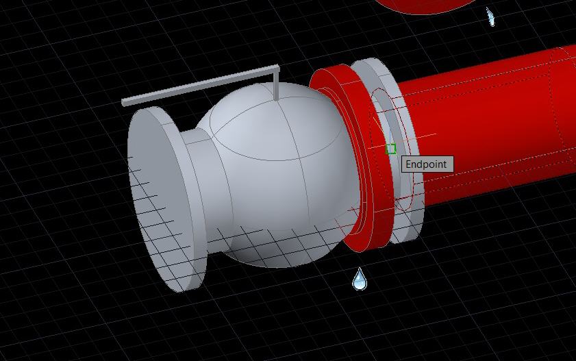
The STUB END in Plant 3D has got a LAP connection by default. In the model this STUB does not even show a connection point on the flange side. It appears as a connector. How can I make this work?
Pic 1 shows no snap-point at flange side
Pic 2 shoes snap-point on the welded side of flange
Solved! Go to Solution.
Solved by Bernd.Gerstenberger. Go to Solution.
5 REPLIES 5
Message 2 of 6
01-13-2013
02:56 PM
- Mark as New
- Bookmark
- Subscribe
- Mute
- Subscribe to RSS Feed
- Permalink
- Report
01-13-2013
02:56 PM
Are you trying to connect to an END osnap? Try the NODE osnap.
Tomislav Golubovic
Technical Specialist - Plant and Infrastructure
Autodesk Australia / New Zealand
Autodesk, Inc.
Autodesk ANZ YouTube Channel
Message 3 of 6
01-15-2013
07:32 PM
- Mark as New
- Bookmark
- Subscribe
- Mute
- Subscribe to RSS Feed
- Permalink
- Report
01-15-2013
07:32 PM
Thanks for your suggestion.
The components connect when I use the NODE snap ut I get error message and there is a leakage. See attachment.
Message 4 of 6
01-15-2013
09:35 PM
- Mark as New
- Bookmark
- Subscribe
- Mute
- Subscribe to RSS Feed
- Permalink
- Report
01-15-2013
09:35 PM
The error message is telling you to check the 3 properties. Check one against the other and see what the difference is. When you find the conflicting properties, you'll have to take steps to rectify it, either by editing the properties again or the connection rules.
Tomislav Golubovic
Technical Specialist - Plant and Infrastructure
Autodesk Australia / New Zealand
Autodesk, Inc.
Autodesk ANZ YouTube Channel
Message 5 of 6
01-18-2013
01:21 AM
- Mark as New
- Bookmark
- Subscribe
- Mute
- Subscribe to RSS Feed
- Permalink
- Report
01-18-2013
01:21 AM
Hi Trygve,
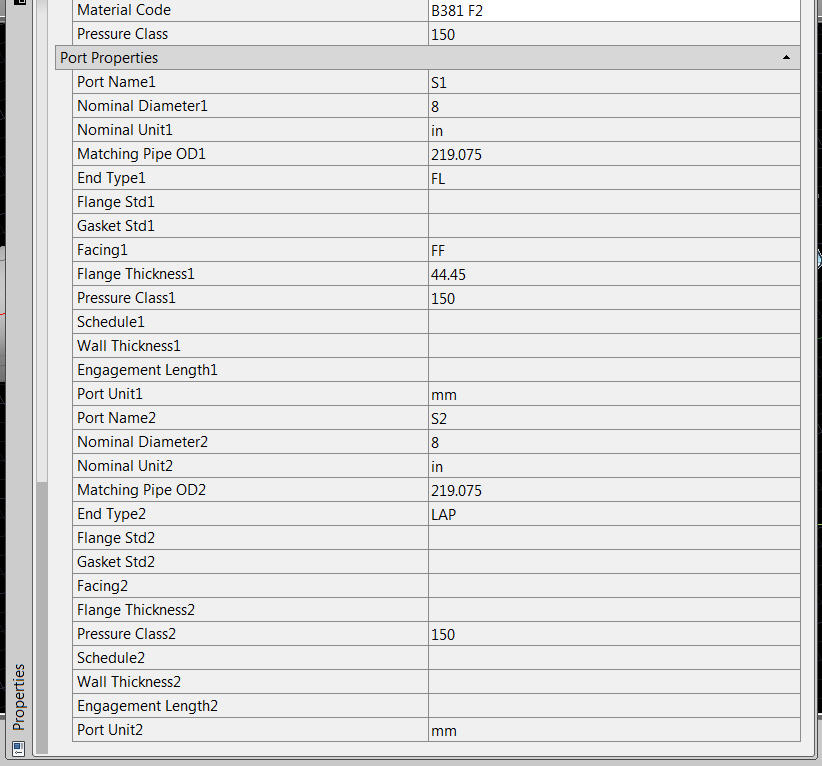
I have looked for the properties of the flange and valve which have attached here. So for a valid connection it is defined in your project that the NominalDiameter, the PressureClass and the Facing of the connected ports are the same.
For your flange I can see that the properties are
for the port S1:
NominalDiameter = 8
PressureClass = 150
Facing = FF
for the port S2:
NominalDiameter = 8
PressureClass = 150
Facing = no value
For your valve the values are
for the port S1:
NominalDiameter = 8
PressureClass = 150
Facing = RF
NominalDiameter = 8
PressureClass = 150
Facing = RF
So the facing for the valves and the flange are different. You have to redefine your properties here, so a match is possible.
Please, inform us if we could help you.
Regards
Bernd
Bernd G.
Senior Product Support Specialist
Message 6 of 6
01-18-2013
01:45 AM
- Mark as New
- Bookmark
- Subscribe
- Mute
- Subscribe to RSS Feed
- Permalink
- Report
01-18-2013
01:45 AM
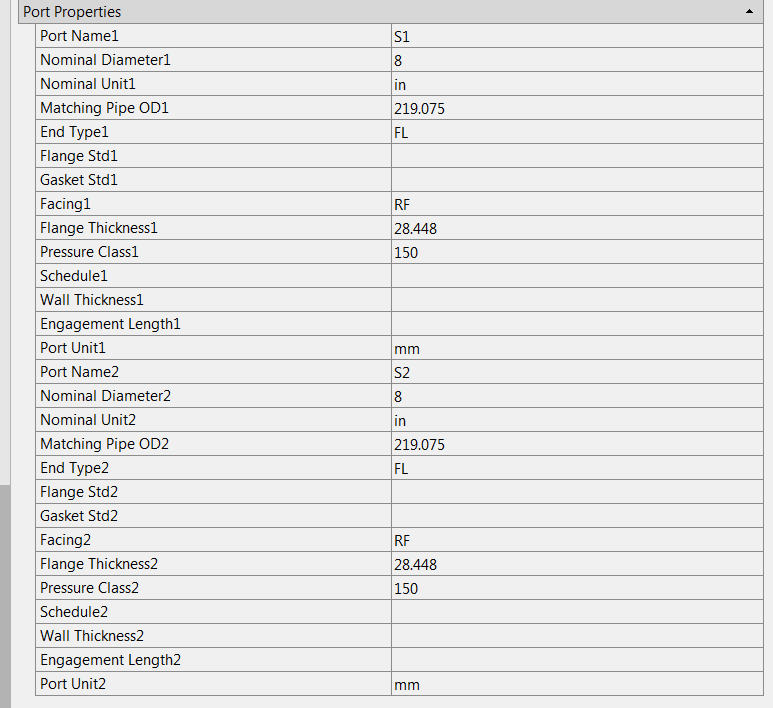
I have found a solution to this problem.
The thing is that the lapped flange is RF in my piping spec while the default Plant 3D catalog only offer FF facing for lapped flange. Did a duplication of the FF lapped flange and changed facing to RF.
Voilà !!!!
Reply
Topic Options
- Subscribe to RSS Feed
- Mark Topic as New
- Mark Topic as Read
- Float this Topic for Current User
- Bookmark
- Subscribe
- Printer Friendly Page

