Community
AutoCAD Plant 3D Forum
Welcome to Autodesk’s AutoCAD Plant 3D Forums. Share your knowledge, ask questions, and explore popular AutoCAD Plant 3D topics.
Turn on suggestions
Auto-suggest helps you quickly narrow down your search results by suggesting possible matches as you type.
Reply
Topic Options
- Subscribe to RSS Feed
- Mark Topic as New
- Mark Topic as Read
- Float this Topic for Current User
- Bookmark
- Subscribe
- Printer Friendly Page
Message 1 of 6
06-03-2011
02:48 PM
- Mark as New
- Bookmark
- Subscribe
- Mute
- Subscribe to RSS Feed
- Permalink
- Report
06-03-2011
02:48 PM
Flex Connectors
I work with a lot of piping that requires flex connectors. I am not a 100% sure how to create something that would look like that in the plant 3d model, I also do not know how I would create an Iso Symbol for it.
The only thing I can think of is getting two flanges and then creating some sort of wavy surface with AutoCAD equivalent of a revolve tool, but that would still leave out how to get it to show on an iso drawing.
5 REPLIES 5
Message 2 of 6
06-05-2011
03:59 PM
- Mark as New
- Bookmark
- Subscribe
- Mute
- Subscribe to RSS Feed
- Permalink
- Report
06-05-2011
03:59 PM
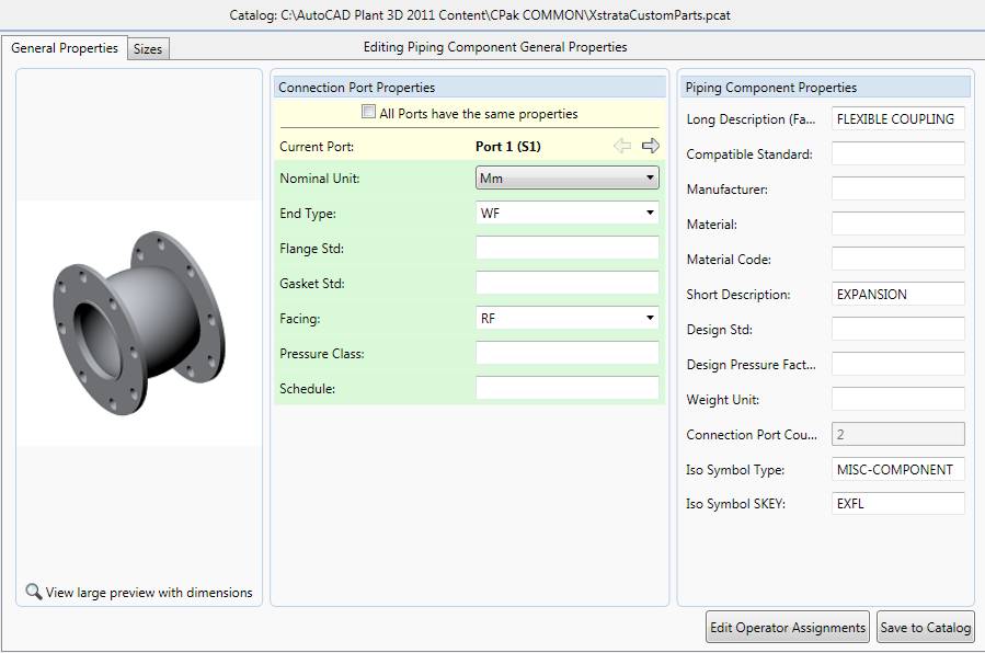
I've got a custom part catalog that I've made up for our stuff.
Roughly the steps are like this:
- Model your flex
- Save it in a good place
- Run 'plantpartconvert' and add the ports, save again.
- Then chuck it into your custom catalog see this attachment (image056.jpg)
- Then add it to your spec.
Note: Iso symbol type & Iso symbol SKEY entries.
Regs.
Dave
Message 3 of 6
06-05-2011
09:07 PM
- Mark as New
- Bookmark
- Subscribe
- Mute
- Subscribe to RSS Feed
- Permalink
- Report
06-05-2011
09:07 PM
I'm having similar issues.
if you use the iso symbol as noted (EXFL Misc-Component) then your iso will work fine as long as there is not any angular misalignment being taken up by the 'Flex Coupling' (plant talks about 'expansion belows' instead of 'flex connectors' - for taking up expansion axialy along the length of the pipe, not for axial misalignment).
If you make a custompart of a flex coupling to connect a misaligned piperun then when the iso is produced (production doesnt seem to work - quick iso does) the flex coupling will show as straight (with dims) and the actual point where the line changes direction moves to the next node on the pipe!
CAD Management 101:
You can do it your own way,
If its done just how I say!
[Metallica:And Justice For All:1988]
You can do it your own way,
If its done just how I say!
[Metallica:And Justice For All:1988]
Message 4 of 6
06-05-2011
10:58 PM
- Mark as New
- Bookmark
- Subscribe
- Mute
- Subscribe to RSS Feed
- Permalink
- Report
06-05-2011
10:58 PM
Just wondering if the 'block offset' isogen symbol would work for that. It might look a little odd though.
See image: isogen symbols.jpg
Otherwise, what I've done for a really odd component is change it to a peice of equipment and just connect to it. Then tag it as an SP item & detail it on another drawing.
Hope this gives you options?
Message 5 of 6
06-06-2011
04:35 PM
- Mark as New
- Bookmark
- Subscribe
- Mute
- Subscribe to RSS Feed
- Permalink
- Report
06-06-2011
04:35 PM
i dont think the block offset will work...the lines arent 'offset', they are 'misaligned'
Ive used the hose symbol (FXFL) its not ideal buut it works the best for the options ive tried.
CAD Management 101:
You can do it your own way,
If its done just how I say!
[Metallica:And Justice For All:1988]
You can do it your own way,
If its done just how I say!
[Metallica:And Justice For All:1988]
Message 6 of 6
06-08-2011
07:42 AM
- Mark as New
- Bookmark
- Subscribe
- Mute
- Subscribe to RSS Feed
- Permalink
- Report
06-08-2011
07:42 AM
I have the model the way I need it to look, I entered in the values for the ISO Symbols, but it wont let me save it.
Thanks for all the help.
Reply
Topic Options
- Subscribe to RSS Feed
- Mark Topic as New
- Mark Topic as Read
- Float this Topic for Current User
- Bookmark
- Subscribe
- Printer Friendly Page

