Community
AutoCAD Map 3D Forum
Welcome to Autodesk’s AutoCAD Map 3D Forums. Share your knowledge, ask questions, and explore popular AutoCAD Map 3D topics.
Turn on suggestions
Auto-suggest helps you quickly narrow down your search results by suggesting possible matches as you type.
Reply
Topic Options
- Subscribe to RSS Feed
- Mark Topic as New
- Mark Topic as Read
- Float this Topic for Current User
- Bookmark
- Subscribe
- Printer Friendly Page
Message 1 of 11
10-24-2013
10:54 PM
- Mark as New
- Bookmark
- Subscribe
- Mute
- Subscribe to RSS Feed
- Permalink
- Report
10-24-2013
10:54 PM
Feature line width
Hello, colleagues!
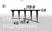
I have liner map feature. I want to apply to lines width like on the picture which I attached. For drawings - polylines I apply differnt "start segment width" and "end segment width" on the "Properties". But how can I do it for liner map features which I connected with "Data connect"?
Thanks all!
Binnat Khalilov
10 REPLIES 10
Message 2 of 11
10-25-2013
04:18 AM
- Mark as New
- Bookmark
- Subscribe
- Mute
- Subscribe to RSS Feed
- Permalink
- Report
10-25-2013
04:18 AM
Hi,
>> But how can I do it for liner map features which I connected with "Data connect"?
I guess that is not possible and will not be possible in the future, the reason for that is that you can only assign properties for the whole object (like color, lineweight, ...) but not properties specific to segments or vertices (like startwidth and endwidth for each polyline-segment are).
- alfred -
------------------------------------------------------------------------------------
Alfred NESWADBA
Ingenieur Studio HOLLAUS ... www.hollaus.at ... blog.hollaus.at ... CDay 2024
------------------------------------------------------------------------------------
(not an Autodesk consultant)
Alfred NESWADBA
Ingenieur Studio HOLLAUS ... www.hollaus.at ... blog.hollaus.at ... CDay 2024
------------------------------------------------------------------------------------
(not an Autodesk consultant)
Message 3 of 11
10-25-2013
05:03 AM
- Mark as New
- Bookmark
- Subscribe
- Mute
- Subscribe to RSS Feed
- Permalink
- Report
10-25-2013
05:03 AM
Then, how can I creat map object like the image which I attached? It is a breastwall symbol in our standart. It may be liner or polygonal type feature.
Binnat Khalilov
Message 4 of 11
10-25-2013
05:15 AM
- Mark as New
- Bookmark
- Subscribe
- Mute
- Subscribe to RSS Feed
- Permalink
- Report
10-25-2013
05:15 AM
Hi,
>> It is a breastwall symbol in our standart
That's a profile/section, isn't it? Do you create them by having the lower and the upper levels as FDO-objects in a SHP/SDF/...?
Can you upload a small sample drawing showing that parts? At the moment I think I don't understand how that is done with GIS-functions (as sections/profiles are at least CAD functionality)
- alfred -
------------------------------------------------------------------------------------
Alfred NESWADBA
Ingenieur Studio HOLLAUS ... www.hollaus.at ... blog.hollaus.at ... CDay 2024
------------------------------------------------------------------------------------
(not an Autodesk consultant)
Alfred NESWADBA
Ingenieur Studio HOLLAUS ... www.hollaus.at ... blog.hollaus.at ... CDay 2024
------------------------------------------------------------------------------------
(not an Autodesk consultant)
Message 5 of 11
10-25-2013
05:40 AM
- Mark as New
- Bookmark
- Subscribe
- Mute
- Subscribe to RSS Feed
- Permalink
- Report
10-25-2013
05:40 AM
Thanks, Alfred for trying help me.
I attached a sample DWG file which I created with the drawing polylines. I want to creat same objects, but using "Style editor" for GIS-files (SDF). It is not profile/sections. It is only map symbol (top view) of breastwalls. And levels or elevations don't required.
Binnat Khalilov
Message 6 of 11
10-25-2013
06:00 AM
- Mark as New
- Bookmark
- Subscribe
- Mute
- Subscribe to RSS Feed
- Permalink
- Report
10-25-2013
06:00 AM
Hi,
>> It is only map symbol (top view) of breastwalls
Well, that it's a new job for GIS ... to fill gaps between two polylines, close to a hatch, but not really a fill object as it does not have a complete border.
It remembers me to a display representation we use for borders of flooding areas in land-use plans. The problem there is that this is not a straight line, but also triangles "running" along with the border. Not to have straight lines means a lot of calculations for how to fit those triangles along the border (e.g. so they don't selfintersect in corners).

Well, back to your situation. I guess there's no function availaible for
a) line-following symbols ...with
b) changing the symbol-scaling along the path ... and
c) finding the scale from the distance to another polyline
It may be solvable by writing a tool for that, then it's just a type of calculation to place the objects between those two lines, not to complicated. More interesting it might be the algorithm for how to find the "correct opposite line".
I'm sorry not to have a solution, if you have some guys beeing able to develop tools, ask them, it might be a chance!
Good luck, - alfred -
------------------------------------------------------------------------------------
Alfred NESWADBA
Ingenieur Studio HOLLAUS ... www.hollaus.at ... blog.hollaus.at ... CDay 2024
------------------------------------------------------------------------------------
(not an Autodesk consultant)
Alfred NESWADBA
Ingenieur Studio HOLLAUS ... www.hollaus.at ... blog.hollaus.at ... CDay 2024
------------------------------------------------------------------------------------
(not an Autodesk consultant)
Message 7 of 11
10-27-2013
02:13 AM
- Mark as New
- Bookmark
- Subscribe
- Mute
- Subscribe to RSS Feed
- Permalink
- Report
10-27-2013
02:13 AM
Alfred, how do you think, can I use a poligonal feature to represent that symbol? And can you send me an example of symbology (.layer file for AutoCAD Map)for borders of flooding areas in land-use plans which used in your country or use you?
Binnat Khalilov
Message 8 of 11
10-27-2013
02:47 AM
- Mark as New
- Bookmark
- Subscribe
- Mute
- Subscribe to RSS Feed
- Permalink
- Report
10-27-2013
02:47 AM
Hi,
>> do you think, can I use a poligonal feature to represent that symbol?
For the triangles themselves? No, I would not do that as in my oppinion a symbol does not have to be represented by polygons/polygon theme. Another reason therefor is that I'm not clear how that symbology would be updated when the 2 border-lines are modified. That might be really tricky.
Depending on the amount of the data a polygonal theme for the symbology might get quite slow in performance.
If you like to create a theme just for that symbology, my way would be to think about a point-theme, where those points are to be created by a tool like _MEASURE in AutoCAD. But there is also a tricky part: how to calculate the scale-factor for each point-symbol depending on the distance to the opposite border/line.
>> And can you send me an example of symbology for borders of flooding areas in land-use plans
I can't, because the symbology here is created with AutoCAD objects (blocks in that case) and not with FDO-objects/styles. And for us we differentiate quite clear between "GIS objects" and "Display objects".
First is transmitted as SHP files, but that is only the border, nothing else (so no triangles)
Second version is then a polyline showing the border plus the triangles showing the side of the water .. and for that there are few apps beeing able to create that display-representations based on the GIS-info.
To make a sample for how to create triangles along a path using FDO: what version of Map3D do you use?
- alfred -
------------------------------------------------------------------------------------
Alfred NESWADBA
Ingenieur Studio HOLLAUS ... www.hollaus.at ... blog.hollaus.at ... CDay 2024
------------------------------------------------------------------------------------
(not an Autodesk consultant)
Alfred NESWADBA
Ingenieur Studio HOLLAUS ... www.hollaus.at ... blog.hollaus.at ... CDay 2024
------------------------------------------------------------------------------------
(not an Autodesk consultant)
Message 9 of 11
10-28-2013
01:15 AM
- Mark as New
- Bookmark
- Subscribe
- Mute
- Subscribe to RSS Feed
- Permalink
- Report
Message 10 of 11
10-28-2013
02:11 AM
- Mark as New
- Bookmark
- Subscribe
- Mute
- Subscribe to RSS Feed
- Permalink
- Report
10-28-2013
02:11 AM
Hi,
please find attached a sample SDF + DWG (both saved in C:\TEMP, for your referencing) It shows a polygon that has triangles as symbol along the border of the polygon and the size of the triangles can be controlled by the property "TestDbl" for every single polygon.
I have not played with the linetype/symbology to be more beatiful (especially the alignment), but I guess you wanted to see how to control a symbol size by a database-value.

HTH, - alfred -
------------------------------------------------------------------------------------
Alfred NESWADBA
Ingenieur Studio HOLLAUS ... www.hollaus.at ... blog.hollaus.at ... CDay 2024
------------------------------------------------------------------------------------
(not an Autodesk consultant)
Alfred NESWADBA
Ingenieur Studio HOLLAUS ... www.hollaus.at ... blog.hollaus.at ... CDay 2024
------------------------------------------------------------------------------------
(not an Autodesk consultant)
Message 11 of 11
10-28-2013
04:45 AM
- Mark as New
- Bookmark
- Subscribe
- Mute
- Subscribe to RSS Feed
- Permalink
- Report
10-28-2013
04:45 AM
Thank you very much, Alfred for try helping me.
I looked you sample. I know simbol style like it, but it is not resolving for my situation. I have asked about it in other forums. And no any ways. I think it is impossible styling for GIS softwares. I will do it with othe-way, I wil use for it simple hatch which showes paralel lines and on the one side line feature with triangles like your example. I don't see any other way.
Thank you very much.
Binnat Khalilov
Reply
Topic Options
- Subscribe to RSS Feed
- Mark Topic as New
- Mark Topic as Read
- Float this Topic for Current User
- Bookmark
- Subscribe
- Printer Friendly Page

