Community
- Forums Home
- >
- AutoCAD Electrical Community
- >
- AutoCAD Electrical Forum
- >
- Re: Terminal Strips vs Terminal Boards - Help Needed
AutoCAD Electrical Forum
Welcome to Autodesk’s AutoCAD Electrical Forums. Share your knowledge, ask questions, and explore popular AutoCAD Electrical topics.
Turn on suggestions
Auto-suggest helps you quickly narrow down your search results by suggesting possible matches as you type.
Reply
Topic Options
- Subscribe to RSS Feed
- Mark Topic as New
- Mark Topic as Read
- Float this Topic for Current User
- Bookmark
- Subscribe
- Printer Friendly Page
Message 1 of 9
03-02-2010
12:10 PM
- Mark as New
- Bookmark
- Subscribe
- Mute
- Subscribe to RSS Feed
- Permalink
- Report
03-02-2010
12:10 PM
Terminal Strips vs Terminal Boards - Help Needed
I wasn't really sure how to title this, so here goes an explanation.
Historically, the company I work for purchases and uses pre built terminal boards. Rather than building terminal strips out of individual blocks, as ACADE seems to want to do. We use 4, 6, 8 and 12pt barrier strip terminal boards. So I'm having a bit of difficulty in merging these two concepts.
If anyone else has this situation I'd appreciate any input. My first instinct is to abandon the TSE approach and just make parent/child components for the terminal boards and be done with it, but I suspect that would come back to haunt me down the road.
--------------
Joe Weaver
Principle Associate Engineer - Nashville Electric Service
P&C Committee Chair – SDS Industry Consortium
Joe Weaver
Principle Associate Engineer - Nashville Electric Service
P&C Committee Chair – SDS Industry Consortium
8 REPLIES 8
Message 2 of 9
03-03-2010
02:05 AM
- Mark as New
- Bookmark
- Subscribe
- Mute
- Subscribe to RSS Feed
- Permalink
- Report
03-03-2010
02:05 AM
I would stick with TSE. Use the supplied schematic terminal symbols.
You can make your own terminal footprints that look like your terminal boards. When you don't use all the ways on the terminal board, just insert spare ways in TSE to make it up to 4, 6, 8 or whatever.
If you don't feel up to making your own terminal footprints, open up a typical footprint and adjust it to suit. Move and re-size the attributes. Once you see how it works you will feel more confident.
BTW I'm not sure parent/child is the right terminology here. It's schematic component/panel footprint. I'm sure someone will correct me...
Message 3 of 9
03-04-2010
07:09 AM
- Mark as New
- Bookmark
- Subscribe
- Mute
- Subscribe to RSS Feed
- Permalink
- Report
03-04-2010
07:09 AM
Ok. Went through with adding terminals and using TSE. The problem I'm coming up with is that if I assign our part number to the terminals, it is now calling for six 6pt terminal boards instead of one. Should I assign our part number to only one terminal per board? Seems like an easy way to introduce errors if someone assigns it twice (or more) by accident.
I do like how thew TSE works, it just doesn't work intuitively for our need.
I do like how thew TSE works, it just doesn't work intuitively for our need.
--------------
Joe Weaver
Principle Associate Engineer - Nashville Electric Service
P&C Committee Chair – SDS Industry Consortium
Joe Weaver
Principle Associate Engineer - Nashville Electric Service
P&C Committee Chair – SDS Industry Consortium
Message 4 of 9
03-04-2010
02:16 PM
- Mark as New
- Bookmark
- Subscribe
- Mute
- Subscribe to RSS Feed
- Permalink
- Report
03-04-2010
02:16 PM
To me, it looks like your first idea is the correct one for what you are
trying to do. Draw some new terminals and set them up as Parent/Child
components. Add a new family to the Cat database or add the terminal strips
to the existing terminals section. Also do a panel footprint for each type
of strip used. You should only need to do one component set to get all the
various strip lengths. Just keep adding child terminals to get the number of
terminals used. Set the cat and mfg on the parent and you are set.
I wouldn't use the TSE for a tag strip as it does not seem to recognise them
properly.
Regards Brad
wrote in message news:6348641@discussion.autodesk.com...
Ok. Went through with adding terminals and using TSE. The problem I'm
coming up with is that if I assign our part number to the terminals, it is
now calling for six 6pt terminal boards instead of one. Should I assign our
part number to only one terminal per board? Seems like an easy way to
introduce errors if someone assigns it twice (or more) by accident.
I do like how thew TSE works, it just doesn't work intuitively for our need.
trying to do. Draw some new terminals and set them up as Parent/Child
components. Add a new family to the Cat database or add the terminal strips
to the existing terminals section. Also do a panel footprint for each type
of strip used. You should only need to do one component set to get all the
various strip lengths. Just keep adding child terminals to get the number of
terminals used. Set the cat and mfg on the parent and you are set.
I wouldn't use the TSE for a tag strip as it does not seem to recognise them
properly.
Regards Brad
Ok. Went through with adding terminals and using TSE. The problem I'm
coming up with is that if I assign our part number to the terminals, it is
now calling for six 6pt terminal boards instead of one. Should I assign our
part number to only one terminal per board? Seems like an easy way to
introduce errors if someone assigns it twice (or more) by accident.
I do like how thew TSE works, it just doesn't work intuitively for our need.
Message 5 of 9
03-05-2010
05:56 AM
- Mark as New
- Bookmark
- Subscribe
- Mute
- Subscribe to RSS Feed
- Permalink
- Report
03-05-2010
05:56 AM
> {quote:title=Guest wrote:}{quote}To me, it looks like your first idea is the correct one for what you are
> trying to do. Draw some new terminals and set them up as Parent/Child
> components. Add a new family to the Cat database or add the terminal strips
> to the existing terminals section. Also do a panel footprint for each type
> of strip used. You should only need to do one component set to get all the
> various strip lengths. Just keep adding child terminals to get the number of
> terminals used. Set the cat and mfg on the parent and you are set.
>
> I wouldn't use the TSE for a tag strip as it does not seem to recognise them
> properly.
>
> Regards Brad
>
Sure looks like that is the way to go. I'm still a little green to this, can I limit the number of connections per point on p/c components like you can in the TSE?
--------------
Joe Weaver
Principle Associate Engineer - Nashville Electric Service
P&C Committee Chair – SDS Industry Consortium
Joe Weaver
Principle Associate Engineer - Nashville Electric Service
P&C Committee Chair – SDS Industry Consortium
Message 6 of 9
03-07-2010
04:43 PM
- Mark as New
- Bookmark
- Subscribe
- Mute
- Subscribe to RSS Feed
- Permalink
- Report
03-07-2010
04:43 PM
You may have to set up a pinlist database for the
terminal boards. Workflow would be to insert the parent terminal, and then
select the catalogue number. When adding the child terminals, ACADE would then
check the pinlist database to count the number of terminals for the selected
board and bring up an alert if it goes over.
terminal boards. Workflow would be to insert the parent terminal, and then
select the catalogue number. When adding the child terminals, ACADE would then
check the pinlist database to count the number of terminals for the selected
board and bring up an alert if it goes over.
The Pinlist database editor is under the cross
referencing flyout in the components drop down menu in ACADE 2008. When you
start it, check and see if the brand of terminal board you use is listed. If it
is, use that one to add your information. If it isn't listed, just type in the
brand name and the editor will create a new group from scratch. Then all you
need to do is add the data. I would use contact type 4 with no coil
pins.
Here is an example of what you should end up with -
4,1;4,2;4,3;4,4
4,1;4,2;4,3;4,4
This is for a 4 terminal board.
Regards Brad
style="BORDER-LEFT: #000000 2px solid; PADDING-LEFT: 5px; PADDING-RIGHT: 0px; MARGIN-LEFT: 5px; MARGIN-RIGHT: 0px">
<drathak> wrote in message>
href="news:6349368@discussion.autodesk.com">news:6349368@discussion.autodesk.com...
{quote:title=Guest wrote:}{quote}To me, it looks like your first idea is the
correct one for what you are
> trying to do. Draw some new terminals
and set them up as Parent/Child
> components. Add a new family to the
Cat database or add the terminal strips
> to the existing terminals
section. Also do a panel footprint for each type
> of strip used. You
should only need to do one component set to get all the
> various strip
lengths. Just keep adding child terminals to get the number of
>
terminals used. Set the cat and mfg on the parent and you are set.
>
> I wouldn't use the TSE for a tag strip as it does not seem to
recognise them
> properly.
>
> Regards Brad
>
Sure looks like that is the way to go. I'm still a little green to
this, can I limit the number of connections per point on p/c components like
you can in the TSE?
Message 7 of 9
03-08-2010
02:50 AM
- Mark as New
- Bookmark
- Subscribe
- Mute
- Subscribe to RSS Feed
- Permalink
- Report
03-08-2010
02:50 AM
Can you have parent and child terminals? Can the parent and child have the same Tag strip and terminal number (or perhaps they must)? Will this allow me to have two separate schematic terminals symbols that are in fact the same terminal? Did not think this was possible. Have I missed something big here?
So many questions... Please enlighten me.
Returning to the original question, is there any limit to the number of "levels" a terminal footprint can have? Could the original query be solved by creating a footprint of the terminal board that is effectively a terminal block with 6 or 8 levels? Then there would be a single part number for the terminal board.
Just an idea. Probably talking complete b*****ks. Edited by: John@Horizon on Mar 8, 2010 10:52 AM
Message 8 of 9
08-21-2013
11:19 AM
- Mark as New
- Bookmark
- Subscribe
- Mute
- Subscribe to RSS Feed
- Permalink
- Report
08-21-2013
11:19 AM
@john wrote:
Returning to the original question, is there any limit to the number of "levels" a terminal footprint can have? Could the original query be solved by creating a footprint of the terminal board that is effectively a terminal block with 6 or 8 levels? Then there would be a single part number for the terminal board.
Just an idea. Probably talking complete b*****ks. Edited by: John@Horizon on Mar 8, 2010 10:52 AM
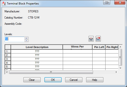
This is sort of the way I ended up going. I insert a normal schematic terminal and in it's properties, set it to the number of levels I have. (4, 6, etc.) and asspciate the other terminals symbols with that one. This way I get only one item in my BOM. Also, I can use the TSE with little problem. (It is just finicky in my opion.)
I've reached the point now, however, of how to show them on the connection diagram. Begining to think I may be able to modify/create a Terminal symbol that will stack into what I want.
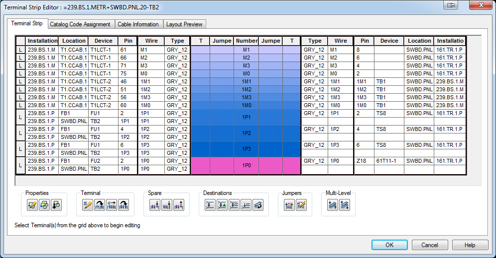
I am attaching a few files for reference. In the first file you can see a bit of a schematic with terminals and the TSE started with one of the ones in the schematic selected for editing. The second file shows the TSE with TB2 opened for editing. As you can see I have the terminals and wiring showing up as you would expect.
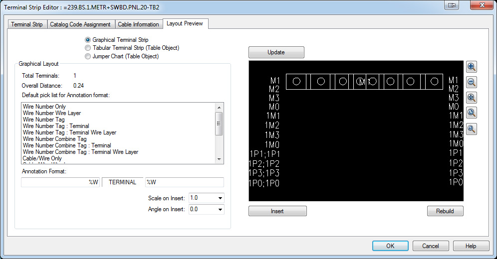
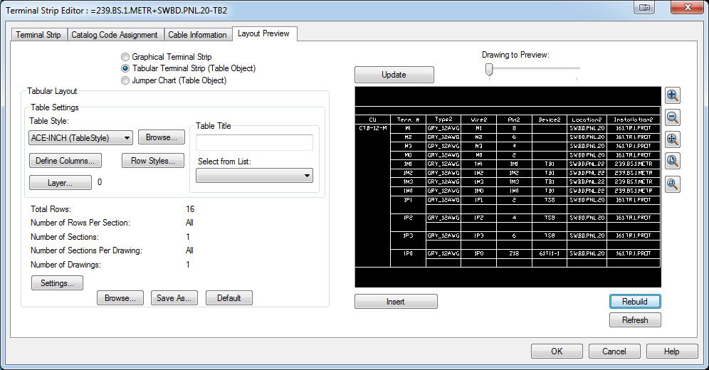
The third files shows the graphical preview. That's where things get wierd. I think some block work will get this fixed, but I'm open to suggestions. The fourth image shows that doing a tabular terminal plan will work. But I'd rather not go that route. (Well the fourth image WOULD show that if the forum would let me post more than three files.)
Any suggestions are most welcome!
--------------
Joe Weaver
Principle Associate Engineer - Nashville Electric Service
P&C Committee Chair – SDS Industry Consortium
Joe Weaver
Principle Associate Engineer - Nashville Electric Service
P&C Committee Chair – SDS Industry Consortium
Message 9 of 9
08-21-2013
11:22 AM
- Mark as New
- Bookmark
- Subscribe
- Mute
- Subscribe to RSS Feed
- Permalink
- Report
08-21-2013
11:22 AM
Ok. Here is the other file and a couple of others showing the Edit Terminal screen and the Terminal Properties screen.
--------------
Joe Weaver
Principle Associate Engineer - Nashville Electric Service
P&C Committee Chair – SDS Industry Consortium
Joe Weaver
Principle Associate Engineer - Nashville Electric Service
P&C Committee Chair – SDS Industry Consortium
Reply
Topic Options
- Subscribe to RSS Feed
- Mark Topic as New
- Mark Topic as Read
- Float this Topic for Current User
- Bookmark
- Subscribe
- Printer Friendly Page

