Community
AutoCAD Electrical Forum
Welcome to Autodesk’s AutoCAD Electrical Forums. Share your knowledge, ask questions, and explore popular AutoCAD Electrical topics.
Turn on suggestions
Auto-suggest helps you quickly narrow down your search results by suggesting possible matches as you type.
Reply
Topic Options
- Subscribe to RSS Feed
- Mark Topic as New
- Mark Topic as Read
- Float this Topic for Current User
- Bookmark
- Subscribe
- Printer Friendly Page
Message 1 of 30
11-15-2006
09:42 PM
- Mark as New
- Bookmark
- Subscribe
- Mute
- Subscribe to RSS Feed
- Permalink
- Report
11-15-2006
09:42 PM
Fan-in Fan-out tutorial
I teach AutoCAD Electrical as in independent consultant in the U.S. and Europe. Everywhere I go there seems to be confusion about implementing the fan-in and fan-out cable feature. I am attaching a drawing I use in class to illustrate applying this tool to a 3-wire cable that connects a proximity sensor on a machine to a terminal strip in a junction box. There are notes on the drawing to explain how it works. I am posting this is a service to those who may appreciate clarification on this issue.
Doug McAlexander

Design Engineer/Consultant/Instructor/Mentor specializing in AutoCAD Electrical training and implementation support
Phone and Web-based Support Plans Available
Phone: (770) 841-8009
www.linkedin.com/in/doug-mcalexander-1a77623
Please Accept as Solution if I helped you. Likes are also much appreciated.
Doug McAlexander
Design Engineer/Consultant/Instructor/Mentor specializing in AutoCAD Electrical training and implementation support
Phone and Web-based Support Plans Available
Phone: (770) 841-8009
www.linkedin.com/in/doug-mcalexander-1a77623
Please Accept as Solution if I helped you. Likes are also much appreciated.
29 REPLIES 29
Message 2 of 30
11-16-2006
05:31 AM
- Mark as New
- Bookmark
- Subscribe
- Mute
- Subscribe to RSS Feed
- Permalink
- Report
11-16-2006
05:31 AM
Thanks doug,
So the vertical 'wire' is not on a wire layer? Seems odd that the fan in/out tool uses a non-wire layer.
So the vertical 'wire' is not on a wire layer? Seems odd that the fan in/out tool uses a non-wire layer.
Message 3 of 30
11-16-2006
06:37 AM
- Mark as New
- Bookmark
- Subscribe
- Mute
- Subscribe to RSS Feed
- Permalink
- Report
11-16-2006
06:37 AM
The vertical "line" is inserted last. As you insert the fan-out sources for example, the program automatically changes the wire segments on the right from layer CABLE_CONDUCTOR to layer _MULTI_WIRE. This is built into the code. Click on Drawing Properties and go to the Styles tab. You will see the name of the layer under the Fan-in Fan-out preferences area. The default is _MULTI_WIRE.
Okay, so as you insert the sources you give them a code of something (whatever you want to call them). These codes are simply what connects the source wires to the destination wires. But if you want to see something useful in the gap below the wire number (potential number) type this in under description. I used V+, V-, and SIG, but you can type whatever makes sense for the function of the cable conductor in your circuit. The help system has you assign a color description, but since I am going to insert cable markers to indicate color, I used the description field of the fan-out sources and fan-in destinations to indicate function (i.e. V+, V-, and SIG). The help system has you insert one parent cable marker in the _MULTI_WIRE line, assign MFG and CAT and blank out the color field. This gets the cable into the BOM and even on the wire list, but it doesn't get the cable wire colors into the from/to list. When you generate your from/to list, be sure to move at least the CBL, CBLWC, CBLMFG, and CBLCAT fields into your report using the Change Report Format button at the lower right of the report generator dialog. You will now see the cable tag, cable wire colors, cable manufacturer, and cable part number n your from/to list. I renamed my fields after moving them into the report format, but that is optional. I will attach a photo of my wire from/to report.
Note: The reason you must wait until after you insert the fan-out sources (also fan-in destinations) to add the vertical "line" is because you could create a dead short across the cable conductors, depending upon what layer you have set to current. Just insert last and place it on the _MULTI_WIRE layer, the same as the "lines" to the right of the fan-out sources or left of the fan-in destinations.
The reason I use a stand-alone cross-reference instead of the standard arrow is that a stand-alone can attach to the end of a line that is not a valid wire. It serves the same purpose, directing me to the other half of the cable.
Doug McAlexander
Design Engineer/Consultant/Instructor/Mentor specializing in AutoCAD Electrical training and implementation support
Phone and Web-based Support Plans Available
Phone: (770) 841-8009
www.linkedin.com/in/doug-mcalexander-1a77623
Please Accept as Solution if I helped you. Likes are also much appreciated.
Message 4 of 30
11-16-2006
06:56 AM
- Mark as New
- Bookmark
- Subscribe
- Mute
- Subscribe to RSS Feed
- Permalink
- Report
11-16-2006
06:56 AM
I spotted an error in the first drawing I attached. Some of the explanation text was pointing to the wrong place and there was no part number assigned to the destination end of the CBL742. Use this one instead.
Doug McAlexander
Design Engineer/Consultant/Instructor/Mentor specializing in AutoCAD Electrical training and implementation support
Phone and Web-based Support Plans Available
Phone: (770) 841-8009
www.linkedin.com/in/doug-mcalexander-1a77623
Please Accept as Solution if I helped you. Likes are also much appreciated.
Message 5 of 30
02-26-2009
09:34 PM
- Mark as New
- Bookmark
- Subscribe
- Mute
- Subscribe to RSS Feed
- Permalink
- Report
02-26-2009
09:34 PM
Dough,
I followed this tutorial it was good to underestand total idea of this tool. But problem is when I want to make a Wire from/to report under CBLWC which should be wire color I assigned to core it comes with signal code of that wire!
did you ever seen that?
Many thanks
I followed this tutorial it was good to underestand total idea of this tool. But problem is when I want to make a Wire from/to report under CBLWC which should be wire color I assigned to core it comes with signal code of that wire!
did you ever seen that?
Many thanks
Message 6 of 30
02-28-2009
10:38 AM
- Mark as New
- Bookmark
- Subscribe
- Mute
- Subscribe to RSS Feed
- Permalink
- Report
02-28-2009
10:38 AM
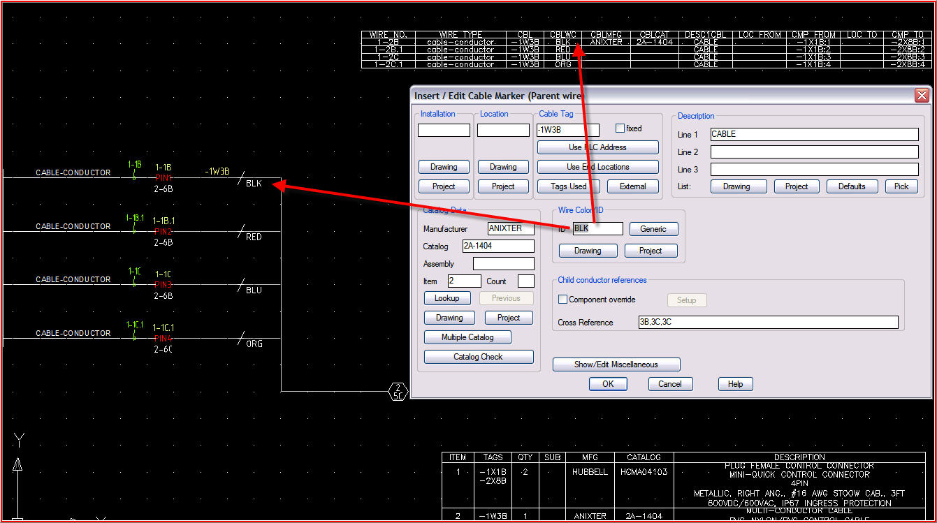
I've not seen that. The wire colors are picked up from the cable markers. The wires themselves appear on the wire list under WLAY1 (wire type) as Cable_Conductor. The CBLWC is whatever color you select or enter in the Edit Component dialog for the cable marker. See attached.
Doug McAlexander
Design Engineer/Consultant/Instructor/Mentor specializing in AutoCAD Electrical training and implementation support
Phone and Web-based Support Plans Available
Phone: (770) 841-8009
www.linkedin.com/in/doug-mcalexander-1a77623
Please Accept as Solution if I helped you. Likes are also much appreciated.
Message 7 of 30
03-02-2009
05:19 PM
- Mark as New
- Bookmark
- Subscribe
- Mute
- Subscribe to RSS Feed
- Permalink
- Report
03-02-2009
05:19 PM
I had a frustrating time during last couple of days struggling to figure out what is happening here in my project but I couldn't. I attached a print screen of my drawing and a sample report of that. As you can see I have some signal source/Destinations ( like ESL, EA, ESD,ESR-A) and some cables which are duplicated with what I have on the other side ( thats what I understood from your way of doing this things). Parent cable's color/ID is empty and child symbols have R and BK colors.
As you can see in report CBLWC shows my signal Descriptions not my wire colors. Edited by: saeedj on Mar 3, 2009 1:22 PM
As you can see in report CBLWC shows my signal Descriptions not my wire colors. Edited by: saeedj on Mar 3, 2009 1:22 PM
Message 8 of 30
03-03-2009
09:02 AM
- Mark as New
- Bookmark
- Subscribe
- Mute
- Subscribe to RSS Feed
- Permalink
- Report
03-03-2009
09:02 AM
It appears that you have two cable markers on the
same wire. The parent cable marker should also have a wire color.
See -1W3B in my previous screen shot example. The parent also carries
the MFG and CAT assignment. I would have to see the actual drawing to know
for certain what is going on, but your drawing doesn't appear to match the
example I posted. The wire to the right of the fan-in/outs should be on
layer Multi_wire. The wire type listed for the cable cores should be
Cable_Conductor. Your fan-in/out signals don't look correct either.
If you can post the drawing I will take a look at it and see what I can
determine.
style="PADDING-RIGHT: 0px; PADDING-LEFT: 5px; MARGIN-LEFT: 5px; BORDER-LEFT: #000000 2px solid; MARGIN-RIGHT: 0px">
<saeedj> wrote in messageI
href="news:6134554@discussion.autodesk.com">news:6134554@discussion.autodesk.com...
had a frustrating time during last couple of days struggling to figure out
what is happening here in my project but I couldn't. I attached a print screen
of my drawing and a sample report of that. As you can see I have some signal
source/Destinations ( like ESL, EA, ESD,ESR-A) and some cables which are
duplicated with what I have on the other side ( thats what I understood from
your way of doing this things). Parent cable's color/ID is empty and child
symbols have R and BK colors. As you can see in report CBLWC shows my signal
Descriptions not my wire colors. Edited by: saeedj on Mar 3, 2009 1:22 PM
Message 9 of 30
03-03-2009
02:34 PM
- Mark as New
- Bookmark
- Subscribe
- Mute
- Subscribe to RSS Feed
- Permalink
- Report
03-03-2009
02:34 PM
Hi Dough,
I attached two drawings which these cables are going across.
some information about them:
1- I put cable markers on the _Multi_Wire layer and I thought your cable_conductor layer is one of your wire layers. Is that right?
2- I have some customised blocks for fan In/Out which wire number is hidden. this is because we don't use standard wire numbers and we need just cable core numbers and signal descriptions.
3- I know symbols and way of showing terminals in termination page will be a bit odd for you but we are going from AutoCAD to ACE and company's policy is to minimize appearance change of drawings for now, as shop guys are get used to them.
I hope every thing is clear and many thanks for your help.
Cheers, Edited by: saeedj on Mar 4, 2009 9:54 AM
Message 10 of 30
03-03-2009
11:58 PM
- Mark as New
- Bookmark
- Subscribe
- Mute
- Subscribe to RSS Feed
- Permalink
- Report
03-03-2009
11:58 PM
I ran a wire list and the cable core colors appear in the report. However the wire layer is diplayed as Yellow_14_THHN though these wire types should be defined according to the cable. I use the Cable_Conductor layer or wire type to draw attention to the fact that the technician should look at the CBLWC column for the specific wire color assignment from the cable.
Another thing you need to do to make this work properly is only insert one parent cable marker per wire. There should not be a C12 marker and a separate R marker. Let the marker for the red wire be a parent and assign the MFG and CAT there. It will then appear in the wire list. Also don't put a cable marker on both sides. You should only put C12 abd C13 on either the source end or the destination end but not both.
I have attached a screen shot of the wire list as it displayed before I made any changes to the drawings. I will post again with a screen shot of the wire list after I made the corrections outlined above.
Doug McAlexander
Design Engineer/Consultant/Instructor/Mentor specializing in AutoCAD Electrical training and implementation support
Phone and Web-based Support Plans Available
Phone: (770) 841-8009
www.linkedin.com/in/doug-mcalexander-1a77623
Please Accept as Solution if I helped you. Likes are also much appreciated.
Message 11 of 30
03-04-2009
12:00 AM
- Mark as New
- Bookmark
- Subscribe
- Mute
- Subscribe to RSS Feed
- Permalink
- Report
03-04-2009
12:00 AM
The attached screen shot shows the wire list after I assigned the Yellow_14_THHN wires to the Cable_Conductor wire layer and fixed the cable markers.
Doug McAlexander
Design Engineer/Consultant/Instructor/Mentor specializing in AutoCAD Electrical training and implementation support
Phone and Web-based Support Plans Available
Phone: (770) 841-8009
www.linkedin.com/in/doug-mcalexander-1a77623
Please Accept as Solution if I helped you. Likes are also much appreciated.
Message 12 of 30
03-04-2009
12:04 AM
- Mark as New
- Bookmark
- Subscribe
- Mute
- Subscribe to RSS Feed
- Permalink
- Report
03-04-2009
12:04 AM
Attached is your project drawings with my modifications that get the data into the wire list and BOM correctly. These are the drawings I used to create the wire list in the previous posting screen shot.
Doug McAlexander
Design Engineer/Consultant/Instructor/Mentor specializing in AutoCAD Electrical training and implementation support
Phone and Web-based Support Plans Available
Phone: (770) 841-8009
www.linkedin.com/in/doug-mcalexander-1a77623
Please Accept as Solution if I helped you. Likes are also much appreciated.
Message 13 of 30
03-04-2009
02:30 PM
- Mark as New
- Bookmark
- Subscribe
- Mute
- Subscribe to RSS Feed
- Permalink
- Report
Message 14 of 30
03-04-2009
09:49 PM
- Mark as New
- Bookmark
- Subscribe
- Mute
- Subscribe to RSS Feed
- Permalink
- Report
03-04-2009
09:49 PM
Well!! it seems fine now but I donno how so I will tell you the story.
At the first I was suspicious about my system but when I got a report from your drawings it was same as your screen shots so I started making my cables like what you said, but I got same results as what I had before. changing any thing even starting from scratches didn't solve my problem. I was getting a random result of wire reports after every "Built / Refresh Project Database". you can see screen shots which each of them are after a database refresh. and then I thought maybe there is somthing about project settings I made it as yours ( from menus) but still results were the same. to make a long story short at the end I copied your wdp file and just added my drawings to that and then every thing became okay ( last screen shot attached).
is there any document about each line of wdp files? to find out what is real difference ? some of the lines are clear but some are not. May be you put some sort of magic on them? 🙂
what is your idea about that random results?
Message 15 of 30
05-20-2010
05:29 AM
- Mark as New
- Bookmark
- Subscribe
- Mute
- Subscribe to RSS Feed
- Permalink
- Report
05-20-2010
05:29 AM
This ones for Doug Mcalexander or anyone who can and is willing to help,
Like some other users the From/To report behaves strangely for me with cable wiring.
I have run the From/To report on your demo10 drawing and the CBLWC colours are being listed as the descriptions from the fan out source signals not the cable markers. (see attached image file)
I have looked at the WDP file you posted earlier in the thread but cannot find a reference how to decipher the settings.
I have tried using your WDP file in my project but still get the same problem.
Any pointers where I am going wrong (acade 2011 64bit)
Regards
David
Message 16 of 30
06-01-2010
09:19 PM
- Mark as New
- Bookmark
- Subscribe
- Mute
- Subscribe to RSS Feed
- Permalink
- Report
06-01-2010
09:19 PM
David, I have attached a more up-to-date example project which I use in my current advanced level course. The older example may have had an error in the report field names. I'm not sure. It's from a few releases ago. Page 1 of the attached project shows both a BOM and Wire List that were created automatically from this new sample project.
Edited by: dougmcalexander on Jun 2, 2010 4:20 AM
Doug McAlexander
Design Engineer/Consultant/Instructor/Mentor specializing in AutoCAD Electrical training and implementation support
Phone and Web-based Support Plans Available
Phone: (770) 841-8009
www.linkedin.com/in/doug-mcalexander-1a77623
Please Accept as Solution if I helped you. Likes are also much appreciated.
Message 17 of 30
06-03-2010
01:43 PM
- Mark as New
- Bookmark
- Subscribe
- Mute
- Subscribe to RSS Feed
- Permalink
- Report
06-03-2010
01:43 PM
Hi Doug, Thanks for the reply.
I understand the theory behind setting up the cable and wires but it just doesn't seem to work for me.
I have attached a modified version of your zip file with two sheets added, one is a cut down sheet from one of my projects with project defaults accepted when added - guess what it works in your project.
The second is a modified version of one of your sheets, changed to work how I do. (The icon menu locations have been changed). On this I have repeated from scratch the circuit from my project drawing but now the cable cores are both the same in the report.
I would be really grateful if you could cast an eye over it I am getting nowhere fast.
By the way on your sheet 1 the wires are 1-1?? the report has wires 1-2??
TIA
David
Message 18 of 30
06-05-2010
01:30 AM
- Mark as New
- Bookmark
- Subscribe
- Mute
- Subscribe to RSS Feed
- Permalink
- Report
06-05-2010
01:30 AM
Hi Doug,
I've just bumped this to show it as a recent thread, during the site update the posting dates seems to have lost a few months.
Message 19 of 30
06-08-2010
10:33 AM
- Mark as New
- Bookmark
- Subscribe
- Mute
- Subscribe to RSS Feed
- Permalink
- Report
06-08-2010
10:33 AM
Without seeing your workflow step-by-step it is hard to determine why this happened. By analyzing your drawing everything appears correct. The funny thing is that when i ran a full rebuild of the project I get D10 and D11 for the cable wire colors instead of the letter "B" for both. But D10 and D11 are your fan-in/fan-out symbol descriptions. They should not appear as cable wire color assignments. I have passed this along to someone at Autodesk for review. It is possible that you have somehow stumbled across a workflow that throws the data manager a curve ball.
Doug McAlexander
Design Engineer/Consultant/Instructor/Mentor specializing in AutoCAD Electrical training and implementation support
Phone and Web-based Support Plans Available
Phone: (770) 841-8009
www.linkedin.com/in/doug-mcalexander-1a77623
Please Accept as Solution if I helped you. Likes are also much appreciated.
Message 20 of 30
06-08-2010
01:16 PM
- Mark as New
- Bookmark
- Subscribe
- Mute
- Subscribe to RSS Feed
- Permalink
- Report
06-08-2010
01:16 PM
Hi Doug,
Thsnks for looking into this for me.
The Fan in source description being used instead of the cable core colour has been my main headache. I have spent days researching the fan in/out method thinking I was doing something fundamentally wrong.
I am begining to think ACADE is fussy regarding drawing settings for the fan in/out to work correctly. I seem to have developed a knack for making it misbehave. As for my work flow I have followed the steps you have outlined in this thread and also the guide here
http://www.augi.com/publications/hotnews.asp?page=1624
but I keep getting the signal description being used instead of the cable colour. I am not happy that I have to adapt the drawing settings to make this work but if that solves it for now then it is a workaround.
Perhaps there is some flaw in the application of the fan in/out ? time will tell, I just know I am now coming under pressure for it to work reliably for me, I have used up all my grace. I'm just pleased you have seen this issue and it's not just me (or is it ?)
Reply
Topic Options
- Subscribe to RSS Feed
- Mark Topic as New
- Mark Topic as Read
- Float this Topic for Current User
- Bookmark
- Subscribe
- Printer Friendly Page

